How to Use Socket PTF08A: Examples, Pinouts, and Specs
Introduction
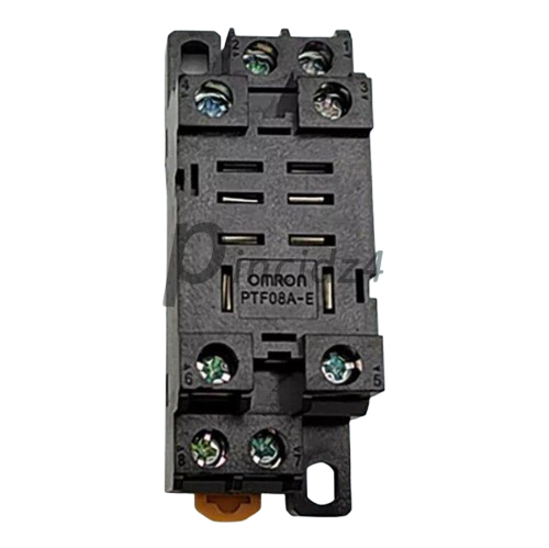
The Socket PTF08A is an 8-pin IC socket designed to facilitate the connection of integrated circuits (ICs) to a printed circuit board (PCB). It allows for the easy insertion and removal of ICs without the need for soldering, making it ideal for prototyping, testing, and applications where IC replacement is frequent. The socket ensures a secure and reliable connection while protecting the IC from potential damage caused by repeated soldering.
Explore Projects Built with Socket PTF08A


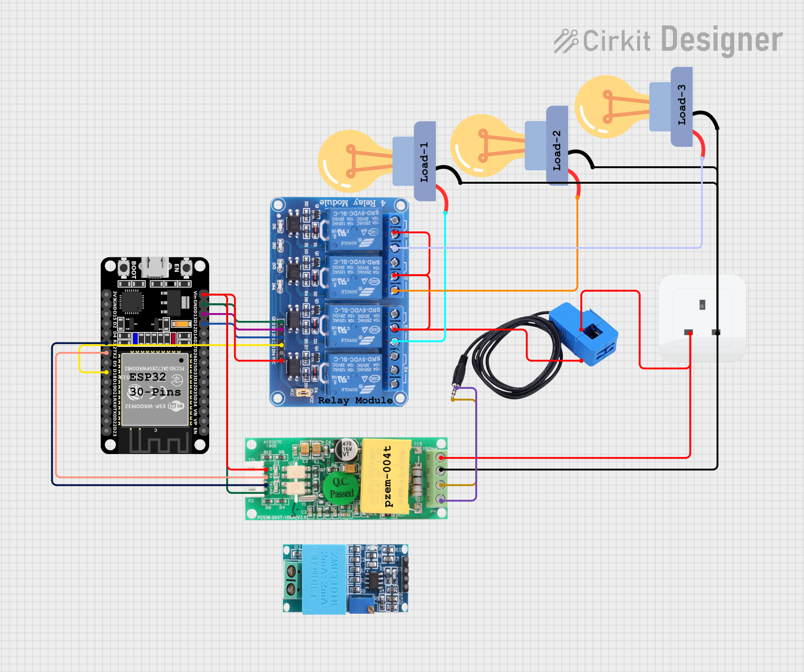
Explore Projects Built with Socket PTF08A
Common Applications and Use Cases
- Prototyping and development of electronic circuits
- IC testing and debugging
- Applications requiring frequent IC replacement or upgrades
- Protection of ICs from heat damage during soldering
- Use in educational and experimental projects
Technical Specifications
The Socket PTF08A is designed to accommodate dual in-line package (DIP) ICs with 8 pins. Below are the key technical details:
General Specifications
| Parameter | Value |
|---|---|
| Number of Pins | 8 |
| Pin Pitch | 2.54 mm (0.1 inch) |
| Material | Thermoplastic body, metal pins |
| Operating Temperature | -40°C to 105°C |
| Contact Resistance | ≤ 20 mΩ |
| Insulation Resistance | ≥ 1000 MΩ |
| Rated Voltage | 250 V AC |
| Rated Current | 1 A |
Pin Configuration and Descriptions
The Socket PTF08A does not have specific pin functionality, as it is a passive component designed to hold ICs. However, the pin layout corresponds directly to the IC it houses. Below is a general representation of the pin configuration:
| Pin Number | Description |
|---|---|
| 1-8 | Direct connection to IC pins |
Usage Instructions
How to Use the Socket PTF08A in a Circuit
- Prepare the PCB: Ensure the PCB has an 8-pin footprint with a 2.54 mm pitch to match the socket.
- Insert the Socket: Place the PTF08A socket into the PCB, aligning its pins with the corresponding holes.
- Solder the Socket: Solder each pin of the socket to the PCB pads, ensuring a clean and secure connection.
- Insert the IC: Carefully align the IC pins with the socket and press it gently into place. Ensure the IC orientation matches the circuit design.
- Connect External Components: Complete the circuit by connecting other components as required.
Important Considerations and Best Practices
- IC Orientation: Always check the orientation of the IC before insertion. Most ICs have a notch or dot indicating pin 1, which should align with the corresponding mark on the socket.
- Avoid Excessive Force: Do not force the IC into the socket, as this may damage the pins or the socket.
- Soldering Precautions: Use a soldering iron with a suitable temperature to avoid damaging the socket or PCB.
- Contact Cleaning: If the socket contacts become dirty or oxidized, clean them gently with isopropyl alcohol to maintain a reliable connection.
Example: Using the Socket PTF08A with an Arduino UNO
The Socket PTF08A can be used to house ICs such as the 555 timer or other DIP ICs in circuits connected to an Arduino UNO. Below is an example of using a 555 timer in an LED blinking circuit:
/* Example: Blinking an LED using a 555 timer IC in a PTF08A socket
   connected to an Arduino UNO. The 555 timer is configured in astable
   mode to generate a square wave signal. */

const int ledPin = 13; // Pin connected to the LED

void setup() {
  pinMode(ledPin, OUTPUT); // Set the LED pin as an output
}

void loop() {
  digitalWrite(ledPin, HIGH); // Turn the LED on
  delay(500);                 // Wait for 500 ms
  digitalWrite(ledPin, LOW);  // Turn the LED off
  delay(500);                 // Wait for 500 ms
}
Note: The 555 timer circuit should be built on a breadboard or PCB with the PTF08A socket, and the output pin of the 555 timer should be connected to the Arduino UNO's digital pin 13.
Troubleshooting and FAQs
Common Issues and Solutions
| Issue | Solution |
|---|---|
| IC not functioning after insertion | Check the IC orientation and ensure it matches the circuit design. |
| Poor connection between IC and PCB | Ensure the socket pins are properly soldered and free of cold joints. |
| IC pins bent during insertion | Straighten the pins carefully using needle-nose pliers before reinserting. |
| Oxidized or dirty socket contacts | Clean the contacts with isopropyl alcohol and a soft brush. |
FAQs
Q: Can the Socket PTF08A be reused?
A: Yes, the socket is designed for repeated use, allowing ICs to be inserted and removed multiple times.
Q: What ICs are compatible with the PTF08A?
A: The socket is compatible with any 8-pin DIP ICs, such as the 555 timer, operational amplifiers, and more.
Q: How do I identify pin 1 on the socket?
A: The socket typically has a notch or marking indicating the location of pin 1, which should align with the IC's pin 1.
Q: Can the socket handle high-frequency signals?
A: While the socket can handle moderate frequencies, it may introduce slight parasitic capacitance and resistance, which could affect very high-frequency signals.
By following this documentation, users can effectively utilize the Socket PTF08A in their electronic projects, ensuring reliable and efficient IC connections.