How to Use Arduino Nano: Examples, Pinouts, and Specs
Introduction
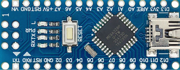
The Arduino Nano is a compact microcontroller board developed by Arduino, based on the ATmega328P microcontroller. It is designed for easy integration into a wide range of electronic projects, offering a small form factor without compromising functionality. The Nano is equipped with digital and analog input/output pins, USB connectivity for programming, and compatibility with the Arduino IDE, making it an excellent choice for both beginners and experienced developers.
Explore Projects Built with Arduino Nano


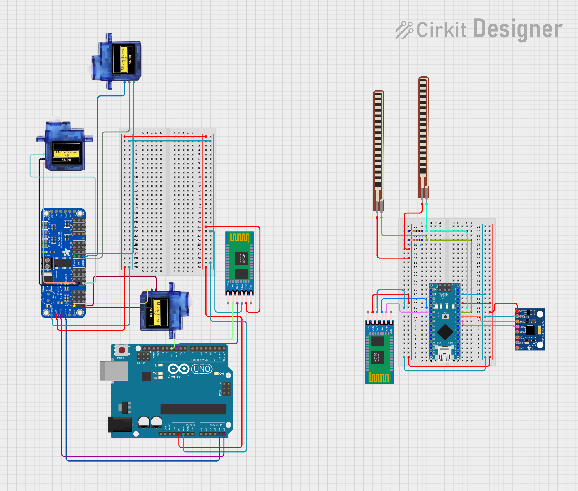
Explore Projects Built with Arduino Nano
Common Applications and Use Cases
- Prototyping and development of embedded systems
- Robotics and automation projects
- IoT (Internet of Things) devices
- Wearable electronics
- Sensor data acquisition and processing
- Educational tools for learning microcontroller programming
Technical Specifications
The Arduino Nano is a versatile board with the following key technical details:
| Specification | Details |
|---|---|
| Microcontroller | ATmega328P |
| Operating Voltage | 5V |
| Input Voltage (recommended) | 7-12V |
| Input Voltage (limit) | 6-20V |
| Digital I/O Pins | 14 (6 of which provide PWM output) |
| Analog Input Pins | 8 |
| DC Current per I/O Pin | 40 mA |
| Flash Memory | 32 KB (2 KB used by bootloader) |
| SRAM | 2 KB |
| EEPROM | 1 KB |
| Clock Speed | 16 MHz |
| USB Connectivity | Mini-B USB port |
| Dimensions | 18 x 45 mm |
| Weight | Approximately 7 grams |
Pin Configuration and Descriptions
The Arduino Nano has a total of 30 pins, including power, digital, and analog pins. Below is a detailed description of the pin configuration:
Power Pins
| Pin | Description |
|---|---|
| VIN | Input voltage to the board when using an external power source (7-12V recommended). |
| 5V | Regulated 5V output from the board. Can be used to power external components. |
| 3.3V | Regulated 3.3V output for low-voltage components. |
| GND | Ground pins (multiple GND pins available). |
| RESET | Resets the microcontroller when connected to GND. |
Digital Pins
| Pin | Description |
|---|---|
| D0-D13 | General-purpose digital input/output pins. |
| PWM | Pins D3, D5, D6, D9, D10, and D11 support PWM output. |
Analog Pins
| Pin | Description |
|---|---|
| A0-A7 | Analog input pins for reading sensor data (10-bit resolution). |
Communication Pins
| Pin | Description |
|---|---|
| TX (D1) | Transmit pin for serial communication. |
| RX (D0) | Receive pin for serial communication. |
| SDA | I2C data line (shared with A4). |
| SCL | I2C clock line (shared with A5). |
Usage Instructions
The Arduino Nano is easy to use and program. Follow these steps to get started:
Step 1: Install the Arduino IDE
- Download and install the Arduino IDE from the official Arduino website: https://www.arduino.cc.
- Connect the Arduino Nano to your computer using a Mini-B USB cable.
Step 2: Select the Board and Port
- Open the Arduino IDE.
- Go to Tools > Board and select Arduino Nano.
- Under Tools > Processor, select ATmega328P (Old Bootloader) if your Nano uses the older bootloader.
- Go to Tools > Port and select the COM port associated with your Nano.
Step 3: Write and Upload Code
Write your code in the Arduino IDE and click the Upload button to program the Nano. Below is an example code to blink an LED connected to pin D13:
// Blink an LED connected to pin D13
// The LED will turn on for 1 second and off for 1 second repeatedly.

void setup() {
  pinMode(13, OUTPUT); // Set pin 13 as an output pin
}

void loop() {
  digitalWrite(13, HIGH); // Turn the LED on
  delay(1000);            // Wait for 1 second
  digitalWrite(13, LOW);  // Turn the LED off
  delay(1000);            // Wait for 1 second
}
Important Considerations and Best Practices
- Ensure the input voltage does not exceed the recommended range (7-12V) to avoid damaging the board.
- Use a proper USB cable to ensure reliable communication and power delivery.
- Avoid drawing more than 40 mA from any single I/O pin to prevent damage to the microcontroller.
- Use external pull-up or pull-down resistors for stable digital input readings if needed.
- When using the Nano in a breadboard, ensure proper alignment of pins to avoid short circuits.
Troubleshooting and FAQs
Common Issues and Solutions
Problem: The Arduino Nano is not recognized by the computer.
- Solution: Ensure the correct drivers are installed. For older Nanos, install the CH340 driver if required.
Problem: The code does not upload to the Nano.
- Solution: Check that the correct board, processor, and port are selected in the Arduino IDE. If using an older Nano, select ATmega328P (Old Bootloader) under Tools > Processor.
Problem: The Nano is not powering on.
- Solution: Verify the power source. If using an external power supply, ensure the voltage is within the recommended range (7-12V).
Problem: Analog readings are unstable.
- Solution: Use proper decoupling capacitors near the analog input pins and ensure a clean power supply.
FAQs
Q: Can the Arduino Nano be powered via USB?
- A: Yes, the Nano can be powered directly through the Mini-B USB port.
Q: How do I reset the Arduino Nano?
- A: Press the reset button on the board or connect the RESET pin to GND momentarily.
Q: Can I use the Arduino Nano for wireless communication?
- A: Yes, you can connect wireless modules like Bluetooth (HC-05/HC-06) or Wi-Fi (ESP8266) to the Nano.
Q: Is the Arduino Nano compatible with shields?
- A: The Nano does not directly support standard Arduino shields, but it can be used with custom shields or breakout boards designed for its pin layout.
By following this documentation, you can effectively integrate the Arduino Nano into your projects and troubleshoot common issues with ease.