Cirkit Designer Logo
Cirkit Designer
Your all-in-one circuit design IDE
Home / 
Component Documentation

How to Use motor and wheels: Examples, Pinouts, and Specs

Image of motor and wheels
Cirkit Designer LogoDesign with motor and wheels in Cirkit Designer

Introduction

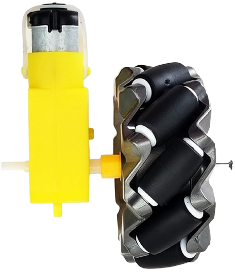
A motor and wheels assembly is a fundamental component in robotics, vehicles, and various automated systems. It consists of an electric motor that converts electrical energy into mechanical energy, which is then used to rotate attached wheels. This assembly is crucial for mobility and is commonly found in applications such as mobile robots, electric vehicles, conveyance systems, and DIY projects.

Explore Projects Built with motor and wheels

Use Cirkit Designer to design, explore, and prototype these projects online. Some projects support real-time simulation. Click "Open Project" to start designing instantly!
Battery-Powered Dual Gearmotor Drive System
Image of electric car: A project utilizing motor and wheels in a practical application
This circuit consists of a 6V battery pack connected in parallel to two DC gearmotors, one for the left wheel and one for the right wheel of a vehicle. The battery provides power directly to both motors, enabling them to run simultaneously. As there is no control circuitry or microcontroller code provided, the motors will run continuously when the circuit is powered.
Cirkit Designer LogoOpen Project in Cirkit Designer
Arduino-Controlled Robotic Vehicle with IR Sensors and L298N Motor Driver
Image of xe do line: A project utilizing motor and wheels in a practical application
This circuit is designed to control a pair of DC gearmotors using an L298N motor driver module, which is interfaced with an Arduino UNO microcontroller. The Arduino is also connected to a 5-channel IR sensor for input, which may be used for line tracking or obstacle detection. Power is supplied by a 9V battery connected through a 2.1mm barrel jack, and the motor driver module regulates this power to drive the left and right gearmotors for a mobile robot platform.
Cirkit Designer LogoOpen Project in Cirkit Designer
ESP32-CAM Controlled Wi-Fi Robot Car
Image of cam car: A project utilizing motor and wheels in a practical application
This circuit is designed to control a two-wheel motorized vehicle using an ESP32-CAM microcontroller. The ESP32-CAM is interfaced with an L298N DC motor driver to control the direction and speed of the motors attached to the wheels. Additionally, the ESP32-CAM is configured to capture images and provide WiFi connectivity for remote control via a web server with a user interface for driving commands.
Cirkit Designer LogoOpen Project in Cirkit Designer
ESP32 and L298N Motor Driver-Based Wi-Fi Controlled Robotic Vehicle with GPS and Metal Detection
Image of Revolutioning Demining: AI Powered Landmine Detection: A project utilizing motor and wheels in a practical application
This circuit is a robotic vehicle control system that uses an ESP32 microcontroller to drive four DC gear motors via an L298N motor driver. It also includes a GPS module for location tracking, a metal detector for object detection, and an ESP32 CAM for capturing images or video, all powered by a 12V battery.
Cirkit Designer LogoOpen Project in Cirkit Designer

Explore Projects Built with motor and wheels

Use Cirkit Designer to design, explore, and prototype these projects online. Some projects support real-time simulation. Click "Open Project" to start designing instantly!
Image of electric car: A project utilizing motor and wheels in a practical application
Battery-Powered Dual Gearmotor Drive System
This circuit consists of a 6V battery pack connected in parallel to two DC gearmotors, one for the left wheel and one for the right wheel of a vehicle. The battery provides power directly to both motors, enabling them to run simultaneously. As there is no control circuitry or microcontroller code provided, the motors will run continuously when the circuit is powered.
Cirkit Designer LogoOpen Project in Cirkit Designer
Image of xe do line: A project utilizing motor and wheels in a practical application
Arduino-Controlled Robotic Vehicle with IR Sensors and L298N Motor Driver
This circuit is designed to control a pair of DC gearmotors using an L298N motor driver module, which is interfaced with an Arduino UNO microcontroller. The Arduino is also connected to a 5-channel IR sensor for input, which may be used for line tracking or obstacle detection. Power is supplied by a 9V battery connected through a 2.1mm barrel jack, and the motor driver module regulates this power to drive the left and right gearmotors for a mobile robot platform.
Cirkit Designer LogoOpen Project in Cirkit Designer
Image of cam car: A project utilizing motor and wheels in a practical application
ESP32-CAM Controlled Wi-Fi Robot Car
This circuit is designed to control a two-wheel motorized vehicle using an ESP32-CAM microcontroller. The ESP32-CAM is interfaced with an L298N DC motor driver to control the direction and speed of the motors attached to the wheels. Additionally, the ESP32-CAM is configured to capture images and provide WiFi connectivity for remote control via a web server with a user interface for driving commands.
Cirkit Designer LogoOpen Project in Cirkit Designer
Image of Revolutioning Demining: AI Powered Landmine Detection: A project utilizing motor and wheels in a practical application
ESP32 and L298N Motor Driver-Based Wi-Fi Controlled Robotic Vehicle with GPS and Metal Detection
This circuit is a robotic vehicle control system that uses an ESP32 microcontroller to drive four DC gear motors via an L298N motor driver. It also includes a GPS module for location tracking, a metal detector for object detection, and an ESP32 CAM for capturing images or video, all powered by a 12V battery.
Cirkit Designer LogoOpen Project in Cirkit Designer

Technical Specifications

General Specifications

  • Motor Type: DC (Direct Current) / Stepper / Servo (Specify as per the actual motor)
  • Rated Voltage: XX V
  • Rated Current: XX A
  • Power Output: XX W
  • Torque: XX Nm
  • Speed: XX RPM (Revolutions Per Minute)
  • Wheel Diameter: XX mm
  • Wheel Width: XX mm
  • Material: (e.g., Rubber, Plastic, Metal)

Pin Configuration and Descriptions

Pin Number Description Notes
1 Motor Positive (+) Connect to power supply (+)
2 Motor Negative (−) Connect to power supply (−)
3 Encoder A (Optional) For speed/position feedback
4 Encoder B (Optional) For speed/position feedback
5 Control Signal (PWM) For speed control (if applicable)

Note: The pin configuration may vary based on the type of motor used.

Usage Instructions

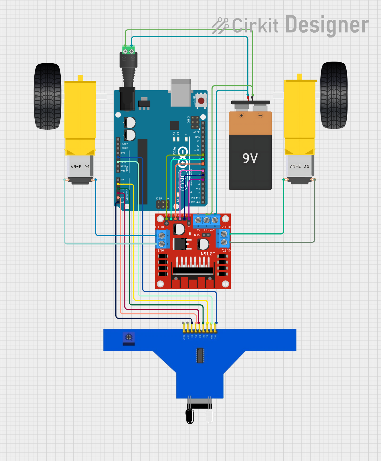
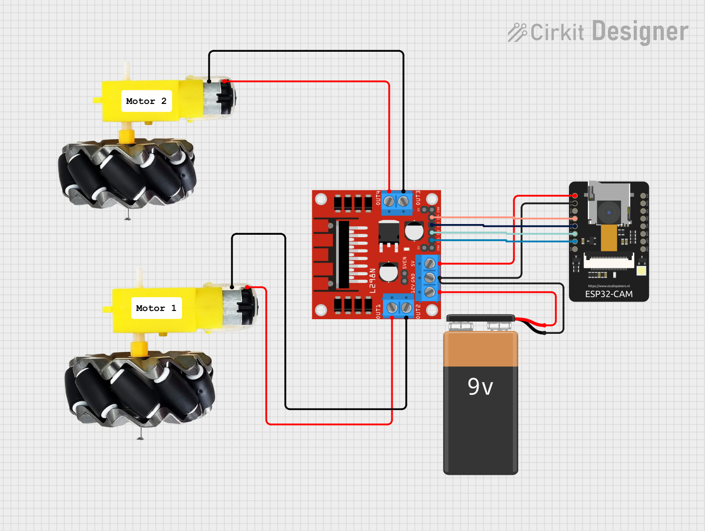
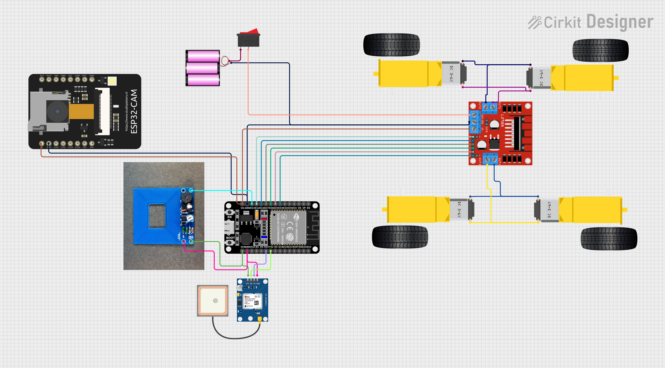
Connecting the Motor

  1. Power Supply: Ensure that the power supply matches the motor's rated voltage and current specifications.
  2. Motor Driver: Use an appropriate motor driver that can handle the motor's power requirements.
  3. Wiring: Connect the motor's positive and negative terminals to the motor driver's output terminals.
  4. Control Signal: If the motor supports speed control via PWM (Pulse Width Modulation), connect the control signal pin to a PWM-capable pin on your microcontroller.

Controlling the Motor with an Arduino UNO

#include <Arduino.h>

// Define motor control pins
const int motorPinPositive = 3; // PWM pin for speed control
const int motorPinNegative = 4; // Direction control (if applicable)

void setup() {
  // Set motor control pins as outputs
  pinMode(motorPinPositive, OUTPUT);
  pinMode(motorPinNegative, OUTPUT);
}

void loop() {
  // Set motor speed and direction
  analogWrite(motorPinPositive, 128); // Set speed (0-255)
  digitalWrite(motorPinNegative, HIGH); // Set direction (HIGH/LOW)

  // Add your code to control the motor based on your application
}

Note: The example code assumes the use of a simple DC motor with PWM speed control. Adjust the code as necessary for the specific type of motor and control method used.

Important Considerations and Best Practices

  • Current Limiting: Ensure that the current drawn by the motor does not exceed the limits of the motor driver and power supply.
  • Heat Dissipation: Motors can generate heat during operation. Provide adequate cooling if necessary.
  • Electrical Noise: Motors can introduce electrical noise into the system. Use appropriate filtering and shielding techniques.
  • Mechanical Mounting: Secure the motor and wheels assembly to prevent vibrations and ensure stable operation.

Troubleshooting and FAQs

Common Issues

  • Motor Does Not Rotate: Check power supply connections, ensure the motor driver is functioning, and verify that the control signals are being sent correctly.
  • Motor Rotates Slowly or Weakly: Confirm that the power supply is providing the correct voltage and current, and that there are no obstructions to the wheel's rotation.
  • Erratic Motor Behavior: Check for loose connections and ensure that PWM signals are being generated correctly.

Solutions and Tips

  • Power Supply Issues: Use a multimeter to verify the voltage and current output of the power supply.
  • Driver Issues: Test the motor driver with a known good motor to determine if the driver is the issue.
  • Signal Integrity: Use an oscilloscope to check the PWM signal's integrity and ensure it is within the expected range.

FAQs

Q: Can I control the speed of the motor? A: Yes, if the motor supports PWM, you can control the speed by varying the duty cycle of the PWM signal.

Q: How do I reverse the direction of the motor? A: For DC motors, you can reverse the polarity of the power supply to the motor. For stepper and servo motors, you will need to follow specific control protocols.

Q: What should I do if the motor is overheating? A: Ensure that the motor is not overloaded and that it has adequate ventilation. Check for any mechanical binding that may cause excessive current draw.

This documentation provides a basic framework for a motor and wheels assembly. Adjust the details according to the specific component you are using.