How to Use Adafruit Feather M4 Express: Examples, Pinouts, and Specs
Introduction
The Adafruit Feather M4 Express is a compact, feature-rich development board designed for versatility and ease of use. It is based on the ATSAMD51 microcontroller and is part of the Feather ecosystem, known for its portable and modular design. This board is ideal for a wide range of applications, from prototyping to final products, including IoT devices, wearable technology, and embedded systems.
Explore Projects Built with Adafruit Feather M4 Express


Explore Projects Built with Adafruit Feather M4 Express
Common Applications and Use Cases
- Rapid prototyping of embedded systems
- IoT device development
- Wearable electronics
- Educational projects and learning platforms
- Battery-powered applications
- DIY electronics and maker projects
Technical Specifications
Key Technical Details
- Microcontroller: ATSAMD51J19
- Clock Speed: 120 MHz
- Flash Memory: 512 KB
- SRAM: 192 KB
- Voltage: 3.3V logic and power
- Digital I/O Pins: 21, with 12 PWM capable
- Analog Input Pins: 6 (12-bit ADC channels)
- Analog Output Pins: 2 (10-bit DAC)
- Interfaces: I2C, SPI, UART
- USB: Native USB support
- Other Features:
- Built-in microSD card slot
- Single NeoPixel RGB LED
- LiPo battery connector and charging circuit
- JST-PH battery connector for 3.7V LiPo batteries
- Built-in 3.3V regulator with 500mA peak current output
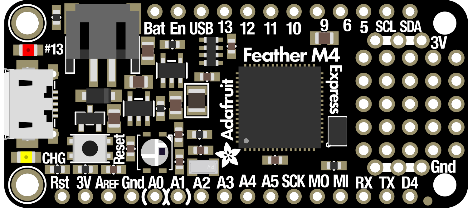
Pin Configuration and Descriptions
| Pin Number | Function | Description |
|---|---|---|
| 1 | GND | Ground |
| 2 | 3V | 3.3V power supply pin |
| 3-8 | A0-A5 | Analog input pins or digital I/O |
| 9-10 | SCK, MISO | SPI communication pins |
| 11-12 | MOSI, SDA | SPI communication pin, I2C data line |
| 13 | SCL | I2C clock line |
| 14-25 | D0-D11 | Digital I/O pins, PWM capable on D5, D6, D9-D11 |
| 26 | RX | UART receive pin |
| 27 | TX | UART transmit pin |
| 28 | EN | Enable pin for the 3.3V regulator |
| 29 | BAT | Battery voltage (connected to battery connector) |
| 30 | USB | Native USB port |
| 31 | NeoPixel | Data input for the onboard NeoPixel LED |
| 32 | RST | Reset pin |
Usage Instructions
How to Use the Component in a Circuit
- Powering the Board: The Feather M4 Express can be powered via USB or a 3.7V LiPo battery. Ensure that the power source is connected properly to avoid damaging the board.
- Connecting Peripherals: Use the GPIO pins to connect sensors, actuators, or other peripherals. Be mindful of the voltage levels and current capabilities of the pins.
- Programming the Board: The board can be programmed using the Arduino IDE or other compatible software. Select "Adafruit Feather M4 (SAMD51)" as the board type in your IDE.
Important Considerations and Best Practices
- Always disconnect the power source before making or altering connections.
- Use a current limiting resistor when connecting LEDs to GPIO pins.
- Avoid drawing more than 500mA from the 3.3V regulator.
- Ensure that the battery is connected with the correct polarity.
- Update the bootloader if necessary, following Adafruit's instructions.
Example Code for Arduino UNO
#include <Adafruit_NeoPixel.h>

#define PIN_NEOPIXEL 8 // Pin connected to the NeoPixel
#define NUMPIXELS    1 // Number of NeoPixels

// Initialize the NeoPixel library.
Adafruit_NeoPixel pixels(NUMPIXELS, PIN_NEOPIXEL, NEO_GRB + NEO_KHZ800);

void setup() {
  pixels.begin(); // Initialize the NeoPixel strip
}

void loop() {
  pixels.setPixelColor(0, pixels.Color(150, 0, 0)); // Set the pixel to red
  pixels.show();   // Send the updated pixel colors to the hardware.
  delay(500);      // Wait for half a second

  pixels.clear();  // Turn off the pixel
  pixels.show();
  delay(500);
}
Troubleshooting and FAQs
Common Issues
- Board not recognized by computer: Ensure the USB cable is properly connected and the board is powered on. Try a different USB port or cable if necessary.
- Unable to upload sketches: Check that the correct board and port are selected in the IDE. Ensure the bootloader is up to date.
- Peripherals not working: Verify connections and ensure that the code is correctly written for the peripherals. Check power requirements and pin configurations.
Solutions and Tips for Troubleshooting
- Reset the board: If the board is unresponsive, press the reset button twice quickly to enter bootloader mode.
- Check solder joints: Poor soldering can lead to unreliable connections. Inspect and rework any questionable joints.
- Consult the forums: The Adafruit forums are a valuable resource for troubleshooting specific issues with the Feather M4 Express.
FAQs
Q: Can I use the Feather M4 Express with a 5V system? A: The board operates at 3.3V. Level shifting is required to interface with 5V systems.
Q: How do I charge the connected LiPo battery? A: The Feather M4 Express has a built-in charging circuit. Simply connect the board to a USB power source, and it will charge the battery.
Q: What is the maximum current draw from a GPIO pin? A: Each GPIO pin can source or sink up to 10 mA. However, the total current from all GPIO pins should not exceed 120 mA.