
How to Use ZS-X11H V2: Examples, Pinouts, and Specs
 Design with ZS-X11H V2 in Cirkit Designer
Introduction
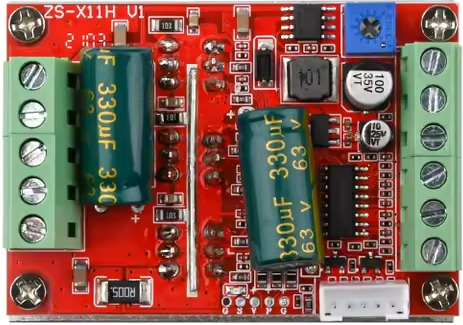
The ZS-X11H V2 is a versatile wireless relay module designed for remote control of electrical devices. Manufactured by China NoName, this module operates using RF (Radio Frequency) signals, making it an ideal choice for automation projects. It allows users to switch devices on and off from a distance, providing convenience and flexibility in various applications.
Explore Projects Built with ZS-X11H V2
 Open Project in Cirkit Designer
 Open Project in Cirkit Designer
 Open Project in Cirkit Designer
 Open Project in Cirkit Designer
Explore Projects Built with ZS-X11H V2
Open Project in Cirkit DesignerOpen Project in Cirkit DesignerOpen Project in Cirkit DesignerOpen Project in Cirkit DesignerCommon Applications and Use Cases
- Home automation systems (e.g., controlling lights, fans, or appliances)
- Industrial automation for remote equipment control
- IoT (Internet of Things) projects
- Wireless control of motors, pumps, or other electrical devices
- Security systems for activating alarms or locking mechanisms
Technical Specifications
The ZS-X11H V2 is designed to provide reliable performance in a compact form factor. Below are its key technical details:
Key Technical Details
| Parameter | Specification |
|---|---|
| Operating Voltage | 5V DC |
| Relay Output Voltage | 250V AC / 30V DC (Max) |
| Relay Output Current | 10A (Max) |
| RF Operating Frequency | 433 MHz |
| Communication Range | Up to 50 meters (line of sight) |
| Module Dimensions | 50mm x 26mm x 18mm |
| Operating Temperature | -20°C to 60°C |
| Power Consumption | < 1W |
Pin Configuration and Descriptions
The ZS-X11H V2 module has a simple pinout for easy integration into circuits. Below is the pin configuration:
| Pin Name | Description |
|---|---|
| VCC | Power input (5V DC) |
| GND | Ground connection |
| IN | Signal input to trigger the relay |
| NO | Normally Open terminal of the relay |
| COM | Common terminal of the relay |
| NC | Normally Closed terminal of the relay |
Usage Instructions
The ZS-X11H V2 is straightforward to use in a variety of circuits. Follow the steps below to integrate it into your project:
How to Use the Component in a Circuit
- Power the Module: Connect the
VCCpin to a 5V DC power source and theGNDpin to ground. - Connect the Load:
- For devices that should be powered when the relay is activated, connect one terminal of the load to the
NO(Normally Open) pin and the other terminal to the power source. - For devices that should be powered when the relay is deactivated, connect one terminal of the load to the
NC(Normally Closed) pin and the other terminal to the power source. - In both cases, connect the
COM(Common) pin to the other side of the power source.
- For devices that should be powered when the relay is activated, connect one terminal of the load to the
- Trigger the Relay: Send a signal to the
INpin to activate the relay. The relay will switch between theNOandNCstates based on the signal.
Important Considerations and Best Practices
- Ensure the load connected to the relay does not exceed the maximum voltage (250V AC / 30V DC) or current (10A).
- Use proper insulation and safety precautions when working with high-voltage loads.
- Avoid placing the module in environments with excessive heat, moisture, or electromagnetic interference.
- For wireless operation, ensure there are no significant obstacles between the transmitter and the module to maintain a strong RF signal.
Example: Using the ZS-X11H V2 with an Arduino UNO
The ZS-X11H V2 can be easily controlled using an Arduino UNO. Below is an example code snippet to toggle the relay:
// Define the pin connected to the relay module
const int relayPin = 7;

void setup() {
  // Set the relay pin as an output
  pinMode(relayPin, OUTPUT);
  // Initialize the relay in the OFF state
  digitalWrite(relayPin, LOW);
}

void loop() {
  // Turn the relay ON
  digitalWrite(relayPin, HIGH);
  delay(5000); // Keep the relay ON for 5 seconds

  // Turn the relay OFF
  digitalWrite(relayPin, LOW);
  delay(5000); // Keep the relay OFF for 5 seconds
}
Note: Connect the IN pin of the ZS-X11H V2 to pin 7 of the Arduino UNO. Ensure the module is powered with 5V from the Arduino's 5V and GND pins.
Troubleshooting and FAQs
Common Issues and Solutions
Relay Not Activating:
- Cause: Insufficient power supply.
- Solution: Ensure the module is powered with a stable 5V DC source.
- Cause: Incorrect signal to the
INpin. - Solution: Verify the signal voltage is within the acceptable range (typically 3.3V to 5V).
RF Signal Not Working:
- Cause: Obstructions or interference in the communication path.
- Solution: Remove obstacles or reduce the distance between the transmitter and the module.
- Cause: Incorrect RF frequency.
- Solution: Ensure the transmitter operates at 433 MHz.
Load Not Switching Properly:
- Cause: Load exceeds the relay's maximum ratings.
- Solution: Use a load within the specified voltage and current limits.
FAQs
Q1: Can the ZS-X11H V2 be used with a 3.3V microcontroller?
A1: Yes, the IN pin can typically accept 3.3V signals, but ensure the module is powered with 5V DC.
Q2: What is the maximum range of the RF signal?
A2: The module can operate up to 50 meters in a line-of-sight environment. Obstacles may reduce this range.
Q3: Can I use this module to control DC motors?
A3: Yes, as long as the motor's voltage and current are within the relay's maximum ratings (30V DC, 10A).
Q4: Is the module compatible with other RF frequencies?
A4: No, the ZS-X11H V2 is designed to operate specifically at 433 MHz.