Cirkit Designer
Your all-in-one circuit design IDE
Home /
Component Documentation
How to Use LED_RED: Examples, Pinouts, and Specs

Introduction
The LED_RED is a red light-emitting diode (LED) manufactured by Custom. It emits red light when an electric current passes through it. This component is widely used as an indicator light in various electronic devices due to its low power consumption, long lifespan, and high visibility.
Explore Projects Built with LED_RED
Battery-Powered RGB LED Control with Pushbuttons

This circuit consists of an RGB LED controlled by three pushbuttons, each corresponding to one of the LED's color channels (Red, Green, and Blue). The pushbuttons are powered by a MAHIR 1.mini power source, allowing the user to manually toggle each color channel of the RGB LED.
Raspberry Pi 4B Controlled Multi-Color LED Indicator
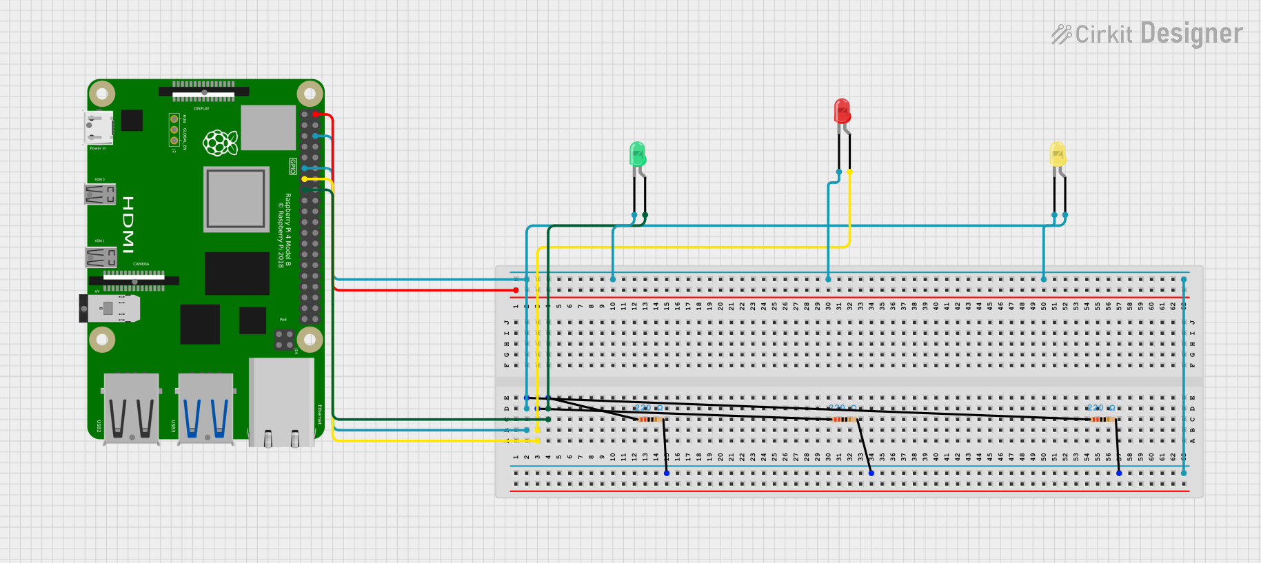
The circuit features a Raspberry Pi 4B microcontroller used to independently control three LEDs (green, red, and yellow) through GPIO pins, with each LED having a series resistor for current limiting. The common cathode configuration for the LEDs allows for simple on/off control signaling or status indication.
Raspberry Pi 4B Controlled Multi-Color LED Indicator
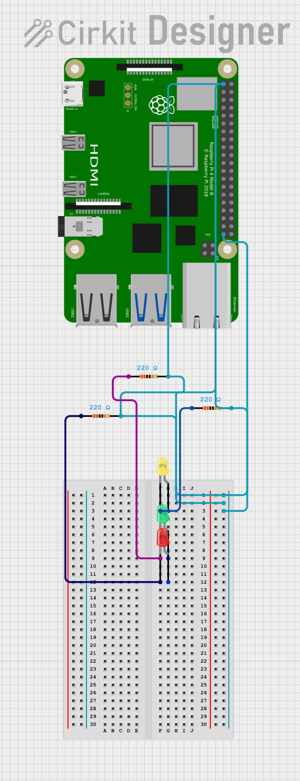
This circuit consists of three LEDs (yellow, green, and red) each with a corresponding 220 Ohm resistor in series. The anodes of the LEDs are connected to their respective resistors, while the cathodes are likely intended to be driven by a Raspberry Pi 4B, as the resistors' other ends are connected to the Pi's 3.3V and GND pins. Without specific code, the functionality of the Raspberry Pi in this circuit cannot be determined, but it is likely used to control the LEDs.
ESP32-Controlled RGB LED Indicator
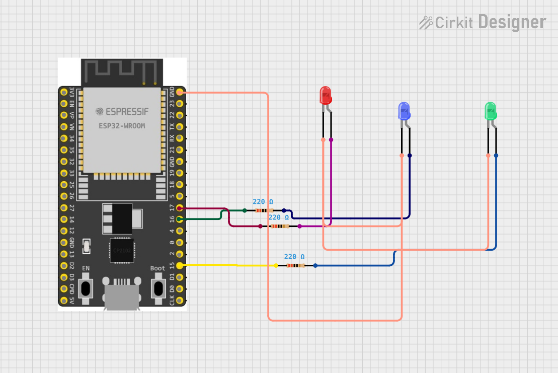
This circuit is designed to control three LEDs (red, green, and blue) using an ESP32 microcontroller. Each LED is connected to a GPIO pin on the ESP32 through a 220-ohm resistor to limit the current. The cathodes of all LEDs are connected to the ground (GND) of the ESP32, and the anodes are individually connected to GPIO pins 15, 16, and 17 through their respective resistors, allowing for independent control of each LED's state (on/off).
Explore Projects Built with LED_RED
Battery-Powered RGB LED Control with Pushbuttons
This circuit consists of an RGB LED controlled by three pushbuttons, each corresponding to one of the LED's color channels (Red, Green, and Blue). The pushbuttons are powered by a MAHIR 1.mini power source, allowing the user to manually toggle each color channel of the RGB LED.
Raspberry Pi 4B Controlled Multi-Color LED Indicator
The circuit features a Raspberry Pi 4B microcontroller used to independently control three LEDs (green, red, and yellow) through GPIO pins, with each LED having a series resistor for current limiting. The common cathode configuration for the LEDs allows for simple on/off control signaling or status indication.
Raspberry Pi 4B Controlled Multi-Color LED Indicator
This circuit consists of three LEDs (yellow, green, and red) each with a corresponding 220 Ohm resistor in series. The anodes of the LEDs are connected to their respective resistors, while the cathodes are likely intended to be driven by a Raspberry Pi 4B, as the resistors' other ends are connected to the Pi's 3.3V and GND pins. Without specific code, the functionality of the Raspberry Pi in this circuit cannot be determined, but it is likely used to control the LEDs.
ESP32-Controlled RGB LED Indicator
This circuit is designed to control three LEDs (red, green, and blue) using an ESP32 microcontroller. Each LED is connected to a GPIO pin on the ESP32 through a 220-ohm resistor to limit the current. The cathodes of all LEDs are connected to the ground (GND) of the ESP32, and the anodes are individually connected to GPIO pins 15, 16, and 17 through their respective resistors, allowing for independent control of each LED's state (on/off).
Common Applications and Use Cases
- Indicator Lights: Used in electronic devices to indicate power status, errors, or other conditions.
- Displays: Utilized in seven-segment displays and other visual indicators.
- Lighting: Employed in decorative lighting, signs, and other applications requiring red illumination.
- Arduino Projects: Frequently used in DIY electronics projects with microcontrollers like the Arduino UNO.
Technical Specifications
Key Technical Details
| Parameter | Value |
|---|---|
| Forward Voltage | 2.0V - 2.2V |
| Forward Current | 20mA |
| Power Rating | 44mW |
| Wavelength | 620nm - 630nm |
| Viewing Angle | 20° - 30° |
| Package Type | 5mm (T-1 3/4) |
Pin Configuration and Descriptions
| Pin Number | Pin Name | Description |
|---|---|---|
| 1 | Anode | Positive terminal (longer lead) |
| 2 | Cathode | Negative terminal (shorter lead) |
Usage Instructions
How to Use the Component in a Circuit
- Identify the Leads: The longer lead is the anode (positive), and the shorter lead is the cathode (negative).
- Connect to Power Source: Connect the anode to the positive terminal of the power source and the cathode to the negative terminal.
- Use a Current-Limiting Resistor: To prevent damage, use a resistor in series with the LED. Calculate the resistor value using Ohm's Law: [ R = \frac{V_{supply} - V_{forward}}{I_{forward}} ] For example, with a 5V supply and a forward voltage of 2.1V: [ R = \frac{5V - 2.1V}{20mA} = 145\Omega ] Use the nearest standard resistor value, which is 150Ω.
Important Considerations and Best Practices
- Polarity: Ensure correct polarity; reversing the connections can damage the LED.
- Current Limiting: Always use a current-limiting resistor to prevent excessive current flow.
- Heat Management: While LEDs are efficient, they can still generate heat. Ensure adequate ventilation if used in high-density applications.
Example Circuit with Arduino UNO
// Example code to blink an LED connected to pin 13 of Arduino UNO

const int ledPin = 13; // Pin number where the LED is connected

void setup() {
  pinMode(ledPin, OUTPUT); // Set the LED pin as an output
}

void loop() {
  digitalWrite(ledPin, HIGH); // Turn the LED on
  delay(1000);                // Wait for 1 second
  digitalWrite(ledPin, LOW);  // Turn the LED off
  delay(1000);                // Wait for 1 second
}
Troubleshooting and FAQs
Common Issues Users Might Face
LED Not Lighting Up:
- Check Polarity: Ensure the anode is connected to the positive terminal and the cathode to the negative terminal.
- Check Connections: Verify all connections are secure and correct.
- Check Resistor: Ensure the current-limiting resistor is of the correct value and properly connected.
LED Flickering:
- Power Supply Stability: Ensure the power supply is stable and not fluctuating.
- Loose Connections: Check for any loose or intermittent connections.
LED Dim:
- Insufficient Current: Ensure the current-limiting resistor is not too high, reducing the current below the required 20mA.
- Power Supply Voltage: Verify the power supply voltage is adequate for the LED's forward voltage.
Solutions and Tips for Troubleshooting
- Multimeter Testing: Use a multimeter to check the voltage across the LED and the current through the circuit.
- Breadboard Testing: Before soldering, test the circuit on a breadboard to ensure all components work correctly.
- Component Substitution: If the LED is not working, try replacing it with a known good LED to rule out component failure.
By following this documentation, users can effectively utilize the LED_RED in their electronic projects, ensuring proper operation and longevity of the component.