How to Use BMI160 Accelerometer Gyro - 6DOF sensor: Examples, Pinouts, and Specs
Introduction
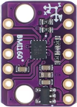
The BMI160 Accelerometer Gyro is a compact 6 Degrees of Freedom (6DOF) sensor that integrates a 3-axis accelerometer and a 3-axis gyroscope into a single chip. Manufactured by Winwin, the BMI160 is designed for use in mobile and wearable devices due to its small form factor and low power consumption. It is ideal for applications such as gesture recognition, pedometer, gaming, navigation, and virtual reality.
Explore Projects Built with BMI160 Accelerometer Gyro - 6DOF sensor
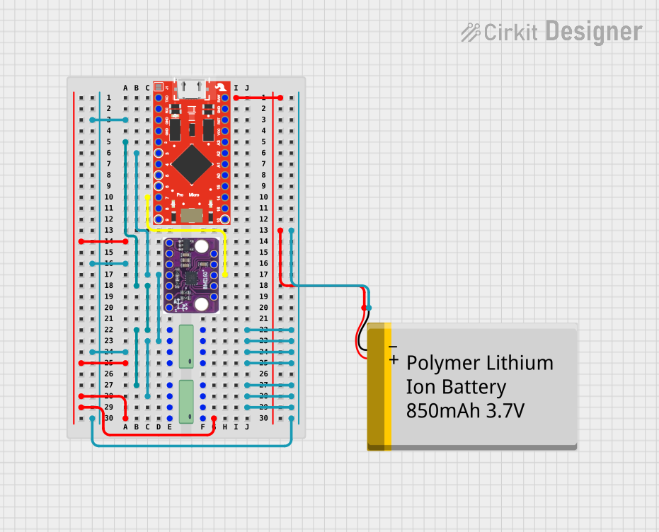
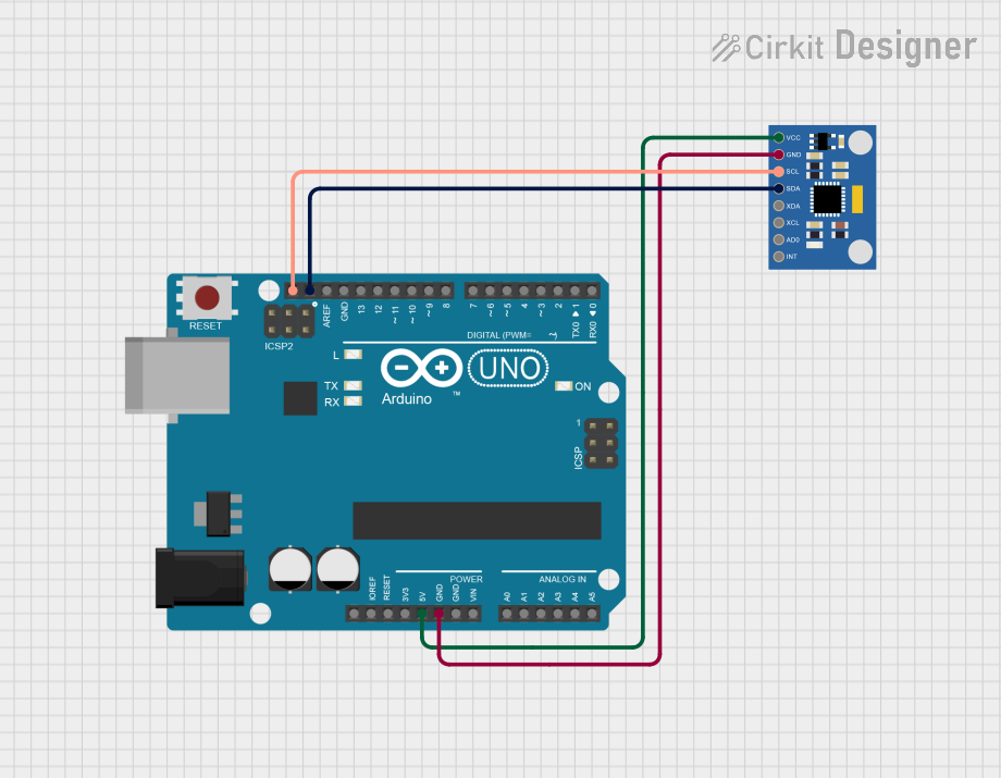
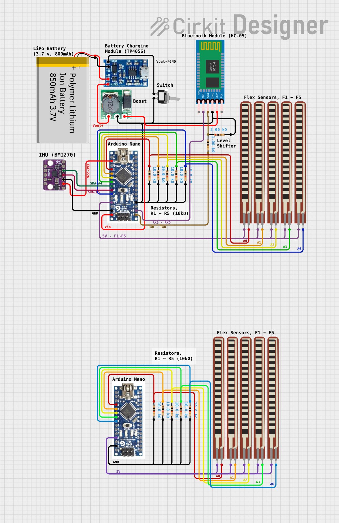
Explore Projects Built with BMI160 Accelerometer Gyro - 6DOF sensor
Technical Specifications
Key Features
- 3-axis, 16-bit accelerometer
- 3-axis, 16-bit gyroscope
- Accelerometer range: ±2g, ±4g, ±8g, ±16g
- Gyroscope range: ±125°/s, ±250°/s, ±500°/s, ±1000°/s, ±2000°/s
- Output data rate (ODR): Accelerometer up to 1600 Hz, Gyroscope up to 3200 Hz
- Interface: I2C and SPI
- Supply voltage: 1.71 V to 3.6 V
- Operating temperature: -40°C to +85°C
Pin Configuration and Descriptions
| Pin Number | Pin Name | Description |
|---|---|---|
| 1 | VDD | Power supply voltage (1.71 V to 3.6 V) |
| 2 | GND | Ground |
| 3 | SCL/SCLK | I2C clock / SPI serial clock |
| 4 | SDA/SDI | I2C data / SPI serial data input |
| 5 | SDO | SPI serial data output |
| 6 | CS | SPI chip select (active low) |
| 7 | INT1 | Interrupt 1 (programmable) |
| 8 | INT2 | Interrupt 2 (programmable) |
Usage Instructions
Integration into a Circuit
- Power Supply: Connect the VDD pin to a power source between 1.71 V and 3.6 V and the GND pin to the ground.
- Communication Interface: Choose between I2C or SPI for communication with a microcontroller like the Arduino UNO.
- For I2C, connect SCL to the I2C clock and SDA to the I2C data.
- For SPI, connect SCLK to the SPI clock, SDI to the SPI data input, SDO to the SPI data output, and CS to the chip select.
- Interrupts: The INT1 and INT2 pins can be configured to output interrupt signals for various sensor events.
Best Practices
- Use pull-up resistors on the I2C lines if they are not already present on the microcontroller board.
- Ensure that the power supply is stable and within the specified voltage range to prevent damage to the sensor.
- When using SPI, ensure that the CS pin is toggled correctly to enable and disable communication with the sensor.
Example Arduino Code
#include <Wire.h>
#include <BMI160Gen.h>

BMI160Gen mySensor;

void setup() {
  Wire.begin();
  Serial.begin(9600);
  if (mySensor.begin(BMI160Gen::I2C_MODE, Wire) == false) {
    Serial.println("BMI160 not found. Please check wiring/power.");
    while (1);
  }
}

void loop() {
  float ax, ay, az, gx, gy, gz;
  mySensor.readMotionSensor(ax, ay, az, gx, gy, gz);

  Serial.print("Accel: ");
  Serial.print(ax); Serial.print(", ");
  Serial.print(ay); Serial.print(", ");
  Serial.println(az);

  Serial.print("Gyro: ");
  Serial.print(gx); Serial.print(", ");
  Serial.print(gy); Serial.print(", ");
  Serial.println(gz);

  delay(100);
}
Troubleshooting and FAQs
Common Issues
- Sensor Not Detected: Ensure that the wiring is correct and that the power supply is within the specified range. Check for proper pull-up resistors on the I2C lines.
- Inaccurate Readings: Calibrate the sensor according to the manufacturer's instructions. Ensure that the sensor is not subjected to mechanical stress or placed near magnetic fields.
- Interrupts Not Working: Verify that the interrupt pins are configured correctly and that the microcontroller's interrupt pins are set up to detect the sensor's interrupt signals.
FAQs
Q: Can the BMI160 be used for both I2C and SPI simultaneously? A: No, the BMI160 can be configured to use either I2C or SPI, but not both at the same time.
Q: What is the purpose of the INT1 and INT2 pins? A: These pins can be programmed to trigger interrupts for specific events like motion detection, data ready, and tap sensing.
Q: How do I calibrate the BMI160 sensor? A: Calibration procedures can vary; refer to the manufacturer's datasheet for specific calibration instructions.
Q: Is the BMI160 suitable for outdoor applications? A: The BMI160 can operate in temperatures ranging from -40°C to +85°C, making it suitable for many outdoor applications. However, it should be protected from moisture and other environmental factors that could damage the sensor.