How to Use ZS-X11D: Examples, Pinouts, and Specs
Introduction
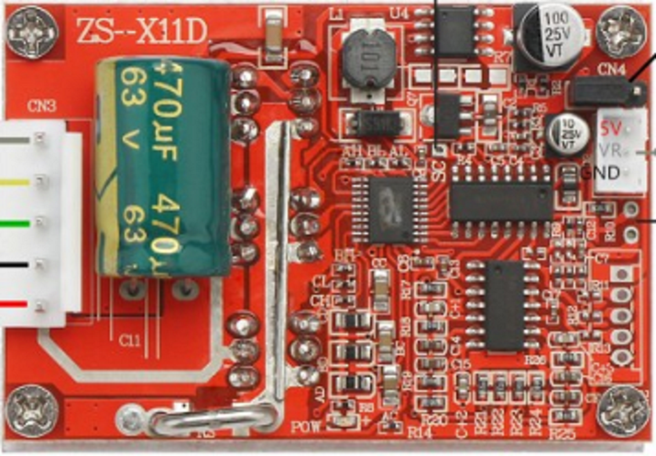
The ZS-X11D is a compact and versatile relay module designed to control high-voltage devices using low-voltage signals. It is equipped with multiple relay outputs, making it ideal for a wide range of applications in automation, home appliances, industrial control systems, and DIY electronics projects. The module provides an efficient and reliable way to interface low-power control circuits with high-power loads.
Explore Projects Built with ZS-X11D


Explore Projects Built with ZS-X11D
Common Applications and Use Cases
- Home automation systems (e.g., controlling lights, fans, or appliances)
- Industrial automation and control
- Robotics and motor control
- DIY electronics projects
- Smart home integration
Technical Specifications
The ZS-X11D relay module is designed to operate efficiently in various environments. Below are its key technical details:
General Specifications
| Parameter | Value |
|---|---|
| Operating Voltage | 5V DC |
| Trigger Voltage | 3.3V to 5V DC |
| Relay Output Voltage | Up to 250V AC or 30V DC |
| Relay Output Current | Up to 10A |
| Number of Relays | 2 (dual-channel) |
| Dimensions | 50mm x 40mm x 18mm |
| Isolation | Optocoupler isolation |
| Indicator LEDs | Power and relay status LEDs |
Pin Configuration and Descriptions
The ZS-X11D module has a straightforward pin layout for easy integration into circuits. Below is the pin configuration:
Input Pins
| Pin Name | Description |
|---|---|
| VCC | Connect to the 5V DC power supply. |
| GND | Connect to the ground of the power supply. |
| IN1 | Control signal for Relay 1. A HIGH signal activates the relay. |
| IN2 | Control signal for Relay 2. A HIGH signal activates the relay. |
Output Terminals (Relay Contacts)
| Terminal Name | Description |
|---|---|
| COM1 | Common terminal for Relay 1. |
| NO1 | Normally Open terminal for Relay 1. Closed when the relay is activated. |
| NC1 | Normally Closed terminal for Relay 1. Open when the relay is activated. |
| COM2 | Common terminal for Relay 2. |
| NO2 | Normally Open terminal for Relay 2. Closed when the relay is activated. |
| NC2 | Normally Closed terminal for Relay 2. Open when the relay is activated. |
Usage Instructions
The ZS-X11D relay module is easy to use and can be integrated into various circuits. Follow the steps below to use the module effectively:
Connecting the Module
- Power Supply: Connect the VCC pin to a 5V DC power source and the GND pin to the ground.
- Control Signals: Connect the IN1 and IN2 pins to the control signals from a microcontroller, such as an Arduino UNO.
- Load Connections:
- For each relay, connect the load to the COM and NO terminals if you want the load to be powered when the relay is activated.
- Use the COM and NC terminals if you want the load to be powered when the relay is deactivated.
Example Circuit with Arduino UNO
Below is an example of how to control the ZS-X11D module using an Arduino UNO:
Circuit Connections
- Connect the VCC pin of the ZS-X11D to the 5V pin of the Arduino.
- Connect the GND pin of the ZS-X11D to the GND pin of the Arduino.
- Connect the IN1 and IN2 pins to digital pins 7 and 8 of the Arduino, respectively.
- Connect the load (e.g., a light bulb) to the relay output terminals (COM and NO).
Example Code
// Example code to control the ZS-X11D relay module with Arduino UNO

// Define the pins connected to the relay module
const int relay1Pin = 7; // IN1 connected to digital pin 7
const int relay2Pin = 8; // IN2 connected to digital pin 8

void setup() {
  // Set relay pins as outputs
  pinMode(relay1Pin, OUTPUT);
  pinMode(relay2Pin, OUTPUT);

  // Initialize relays to OFF state
  digitalWrite(relay1Pin, LOW);
  digitalWrite(relay2Pin, LOW);
}

void loop() {
  // Turn on Relay 1
  digitalWrite(relay1Pin, HIGH);
  delay(1000); // Keep Relay 1 on for 1 second

  // Turn off Relay 1 and turn on Relay 2
  digitalWrite(relay1Pin, LOW);
  digitalWrite(relay2Pin, HIGH);
  delay(1000); // Keep Relay 2 on for 1 second

  // Turn off both relays
  digitalWrite(relay2Pin, LOW);
  delay(1000); // Wait for 1 second before repeating
}
Important Considerations and Best Practices
- Ensure the power supply voltage matches the module's operating voltage (5V DC).
- Do not exceed the relay's maximum voltage and current ratings (250V AC/30V DC, 10A).
- Use proper insulation and safety precautions when working with high-voltage loads.
- Avoid rapid switching of the relays to prevent wear and tear.
Troubleshooting and FAQs
Common Issues and Solutions
Relays Not Activating:
- Ensure the VCC and GND pins are properly connected to a 5V power source.
- Verify that the control signals (IN1 and IN2) are within the acceptable voltage range (3.3V to 5V).
Load Not Powering On:
- Check the wiring of the load to the relay output terminals (COM, NO, NC).
- Ensure the load's power source is properly connected and functional.
Module Overheating:
- Ensure the load does not exceed the relay's maximum current rating (10A).
- Use a heatsink or cooling mechanism if the module operates continuously under high loads.
FAQs
Q: Can the ZS-X11D be used with a 3.3V microcontroller?
A: Yes, the module can be triggered with a 3.3V control signal, but ensure the power supply to the module is 5V DC.
Q: Is the module optically isolated?
A: Yes, the ZS-X11D features optocoupler isolation to protect the control circuit from high-voltage spikes.
Q: Can I control both AC and DC loads with this module?
A: Yes, the ZS-X11D can control both AC (up to 250V) and DC (up to 30V) loads, provided the current does not exceed 10A.
Q: How can I test the module without a microcontroller?
A: You can manually apply a 5V signal to the IN1 or IN2 pins to activate the relays. Ensure proper load connections before testing.
By following this documentation, you can effectively use the ZS-X11D relay module in your projects.