How to Use Vcc: Examples, Pinouts, and Specs
Introduction
VCC, an acronym for Voltage at the Collector terminal, is a term commonly used in electronic circuits to denote the positive supply voltage with respect to the common ground. It is a critical parameter in the design and operation of circuits, particularly in digital electronics and microcontroller applications. VCC is not a component itself but a label used to indicate the positive voltage supply rail in a circuit diagram.
Explore Projects Built with Vcc

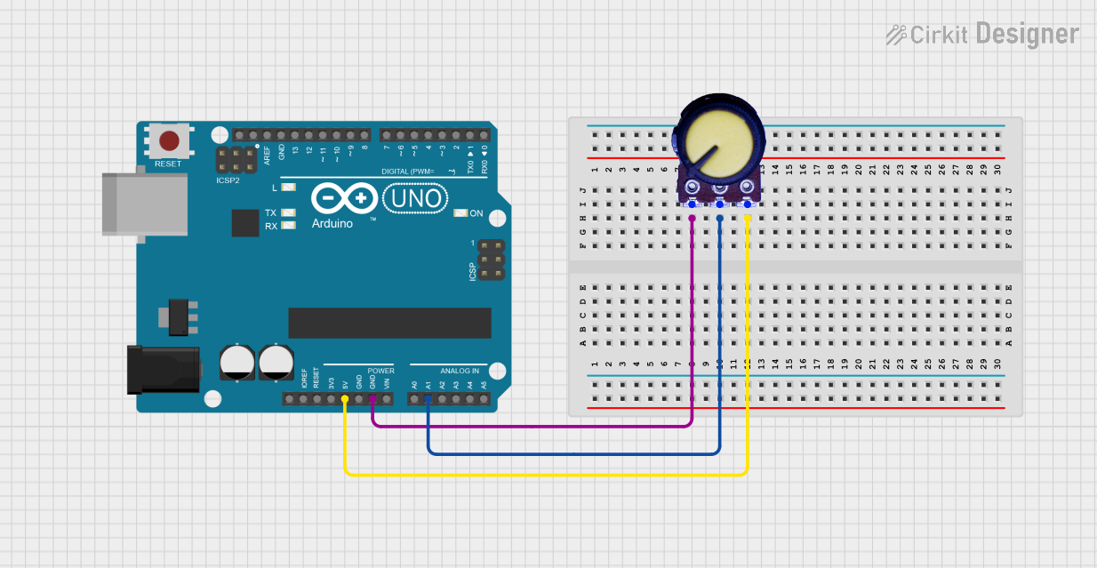
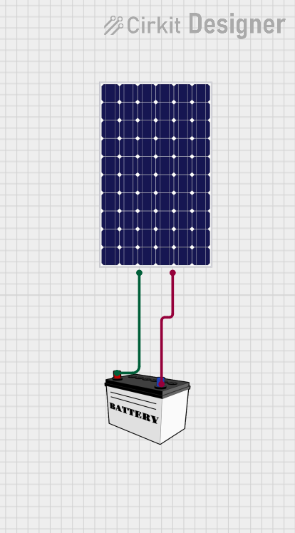
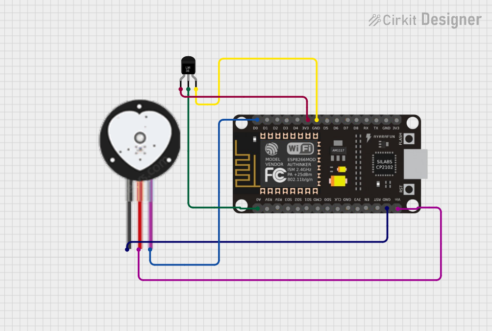
Explore Projects Built with Vcc
Common Applications and Use Cases
- Powering integrated circuits (ICs)
- Supplying voltage to microcontrollers, such as Arduino boards
- Biasing transistors in amplifiers and switches
- Providing the reference voltage for analog-to-digital converters (ADCs)
Technical Specifications
Since VCC is a concept rather than a physical component, the technical specifications will vary depending on the requirements of the electronic device or circuit. Below are general guidelines for VCC specifications in various contexts.
| Specification | Description |
|---|---|
| Voltage Range | Typically ranges from 3.3V to 5V for logic ICs, and up to 12V or higher for power circuits. |
| Current Rating | Depends on the total current consumption of the connected components. |
| Power Rating | Determined by the product of the voltage and the maximum current draw. |
Usage Instructions
How to Use VCC in a Circuit
- Identify the VCC Pin: Refer to the datasheet of the component to locate the VCC pin(s).
- Connect to Power Supply: Connect the VCC pin to the positive terminal of a power supply that matches the voltage requirements.
- Ground Reference: Ensure that the ground (GND) of the power supply is connected to the common ground of the circuit.
- Decoupling Capacitors: Place decoupling capacitors near the power pins of ICs to stabilize VCC and filter out noise.
Important Considerations and Best Practices
- Voltage Compatibility: Ensure that the VCC supplied matches the voltage level required by the components in the circuit.
- Current Limitations: The power supply should be capable of providing sufficient current for all components without exceeding its rating.
- Heat Dissipation: Be mindful of heat generation if the current draw is significant; use appropriate heat sinks if necessary.
- Short Circuit Protection: Implement fuses or current-limiting resistors to protect against short circuits.
Troubleshooting and FAQs
Common Issues
- Voltage Drops: If the voltage at the VCC pin is lower than expected, check for poor connections or excessive current draw.
- Overheating: Components getting too hot may indicate that the VCC is too high or that there is excessive current flow.
- Intermittent Operation: This could be due to unstable VCC caused by insufficient decoupling or a noisy power supply.
Solutions and Tips for Troubleshooting
- Measure Voltage: Use a multimeter to check the voltage level at the VCC pin.
- Check Connections: Ensure all connections are secure and free from corrosion or damage.
- Review Decoupling: Verify that decoupling capacitors are correctly placed and of appropriate value.
FAQs
Q: Can I use a 9V battery for VCC? A: Yes, if the circuit components can operate at 9V. However, voltage regulation may be necessary to provide a stable VCC.
Q: What happens if VCC is too high? A: Exceeding the voltage rating of components can lead to permanent damage or failure.
Q: Is VCC the same as VDD? A: VCC and VDD are similar concepts but are used in different contexts. VCC is typically used for bipolar junction transistors (BJTs), while VDD is used for field-effect transistors (FETs) and CMOS technology.
Example Code for Arduino UNO
// Define the VCC pin for Arduino UNO
const int VccPin = 5; // Assuming we use digital pin 5 as a VCC source

void setup() {
  // Set the VccPin as OUTPUT to provide power
  pinMode(VccPin, OUTPUT);
  // Set the VccPin HIGH to supply 5V
  digitalWrite(VccPin, HIGH);
}

void loop() {
  // Your code here to interact with components powered by the VccPin
}
Note: The above code snippet demonstrates how to use an Arduino digital pin as a VCC source for low-power applications. Ensure that the current draw does not exceed the pin's maximum current rating (typically 20-40mA for Arduino UNO).