
How to Use 12 volt battery charger: Examples, Pinouts, and Specs
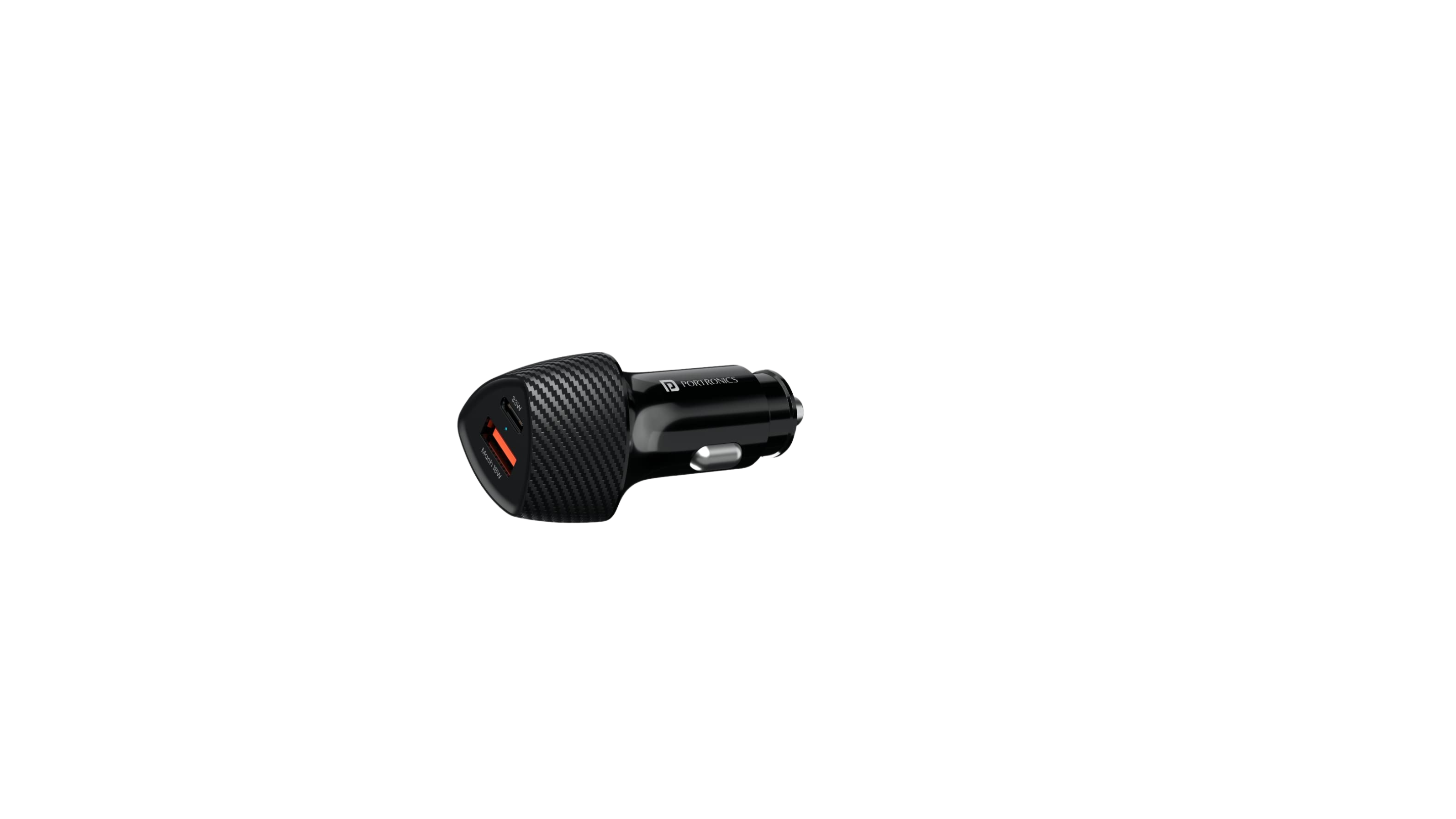
 Design with 12 volt battery charger in Cirkit Designer
Introduction
A 12-volt battery charger is an electronic device designed to replenish the charge in 12-volt batteries, commonly used in automotive, marine, and recreational vehicle (RV) applications. These chargers restore the battery's voltage by applying a controlled electric current, ensuring that the battery is maintained at an optimal charge level for extended life and performance.
Explore Projects Built with 12 volt battery charger
 Open Project in Cirkit Designer
 Open Project in Cirkit Designer
 Open Project in Cirkit Designer
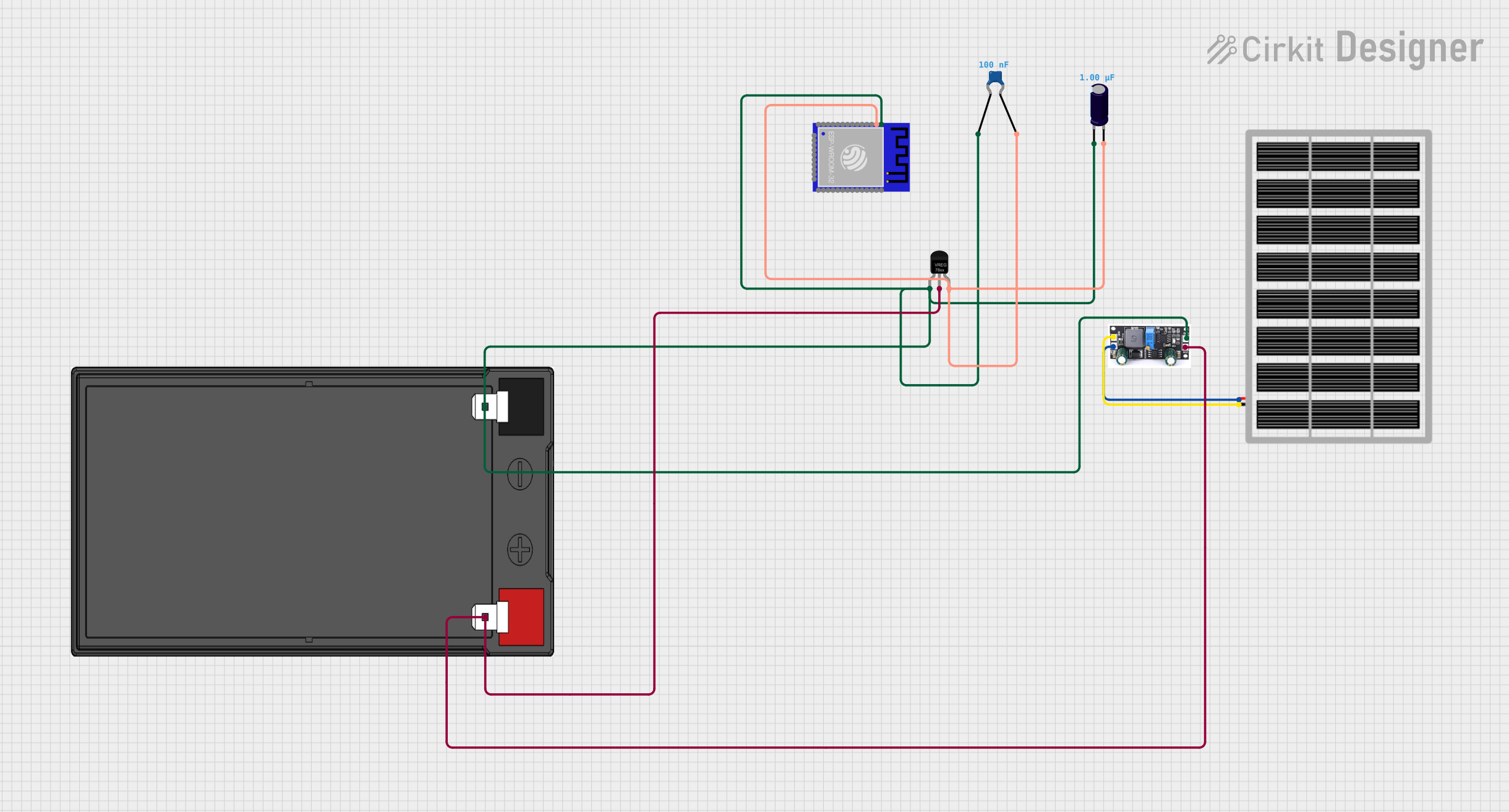
 Open Project in Cirkit Designer
Explore Projects Built with 12 volt battery charger

 Open Project in Cirkit Designer
 Open Project in Cirkit Designer
 Open Project in Cirkit Designer
 Open Project in Cirkit Designer
Common Applications and Use Cases
- Charging automotive batteries in cars, motorcycles, and trucks
- Maintaining charge levels in marine batteries for boats and personal watercraft
- Powering up RV batteries for campers and trailers
- Providing energy to backup power systems and uninterruptible power supplies (UPS)
Technical Specifications
Key Technical Details
- Input Voltage: 110-240V AC (depending on model)
- Output Voltage: 12V DC
- Charging Current: Varies by model (e.g., 2A, 5A, 10A)
- Charging Stages: Multi-stage (e.g., Bulk, Absorption, Float)
- Battery Type Compatibility: Lead-acid, AGM, Gel, etc.
Pin Configuration and Descriptions
| Pin Number | Description | Notes |
|---|---|---|
| 1 | AC Input (Live) | Connect to AC power source |
| 2 | AC Input (Neutral) | Connect to AC power source |
| 3 | Ground | Connect to earth ground |
| 4 | DC Output (+) | Connect to battery positive |
| 5 | DC Output (-) | Connect to battery negative |
Usage Instructions
How to Use the Component in a Circuit
- Safety First: Ensure that the charger is unplugged from the AC power source before making any connections.
- Connect to Battery: Attach the positive (red) charger clip to the positive terminal of the battery, and the negative (black) charger clip to the negative terminal.
- Power Up: Plug the charger into an AC power outlet.
- Set Charging Mode: If the charger has selectable modes, choose the appropriate one for your battery type and desired charge rate.
- Monitor: Some chargers have indicators or digital displays to show the charging progress. Monitor these and disconnect the charger once the battery is fully charged.
Important Considerations and Best Practices
- Always follow the manufacturer's instructions for your specific charger model.
- Do not charge frozen or damaged batteries.
- Ensure good ventilation while charging to dissipate heat and gases.
- Use the charger in a dry location to prevent electrical hazards.
- Regularly inspect the charger and cables for wear or damage.
Troubleshooting and FAQs
Common Issues Users Might Face
- Charger Not Powering On: Check the AC outlet and power cord for proper connection.
- Battery Not Charging: Ensure that the battery terminals and charger clips are clean and making good contact.
- Charger Overheating: Disconnect the charger and allow it to cool. Ensure it's used in a well-ventilated area.
Solutions and Tips for Troubleshooting
- If the charger has a fuse, check if it needs replacing.
- Confirm that the battery voltage matches the charger's output voltage.
- Check for any settings or switches that may be incorrectly set on the charger.
FAQs
- Q: Can I leave my charger connected to the battery indefinitely?
- A: It depends on the charger. Some have a maintenance mode that allows for long-term connection without overcharging the battery.
- Q: How do I know when my battery is fully charged?
- A: Most chargers have an indicator light or display showing the charge status. When it indicates "Full" or stops charging, the battery is charged.
- Q: Can this charger be used for non-automotive batteries?
- A: Yes, as long as they are 12-volt batteries and compatible with the charger's specifications.
Arduino UNO Connection Example
While a 12-volt battery charger is not typically interfaced directly with an Arduino UNO, you can use the Arduino to monitor the charging process. Below is a simple example using a voltage divider and the Arduino's analog input to read the battery voltage.
// Define the analog pin connected to the voltage divider
const int batteryPin = A0;

void setup() {
  // Begin serial communication at 9600 baud rate
  Serial.begin(9600);
}

void loop() {
  // Read the value from the voltage divider
  int sensorValue = analogRead(batteryPin);
  // Convert the reading to voltage (for a 5V Arduino)
  float batteryVoltage = sensorValue * (5.0 / 1023.0) * 2; // Multiply by 2 due to the voltage divider

  // Print the battery voltage to the Serial Monitor
  Serial.print("Battery Voltage: ");
  Serial.println(batteryVoltage);

  // Wait for a second before taking another reading
  delay(1000);
}
Note: The code above assumes a simple voltage divider circuit is used to step down the 12V to a safe level for the Arduino analog input. Always ensure that the voltage does not exceed the maximum rating for the Arduino pin (5V for most models).
Remember to adjust the voltage divider calculation based on the actual resistors used in your circuit. The example assumes two equal resistors, halving the voltage.