
How to Use Darlington Driver: Examples, Pinouts, and Specs
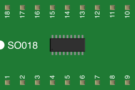
 Design with Darlington Driver in Cirkit Designer
Introduction
A Darlington Driver is a transistor configuration that combines two bipolar junction transistors (BJTs) to achieve a significantly higher current gain compared to a single transistor. This configuration allows the Darlington Driver to amplify small input currents into much larger output currents, making it suitable for driving high-current loads.
Common applications of Darlington Drivers include:
- Motor control in robotics and industrial systems
- Switching high-power loads such as relays, solenoids, and lamps
- LED arrays and display drivers
- Signal amplification in audio and sensor circuits
Explore Projects Built with Darlington Driver
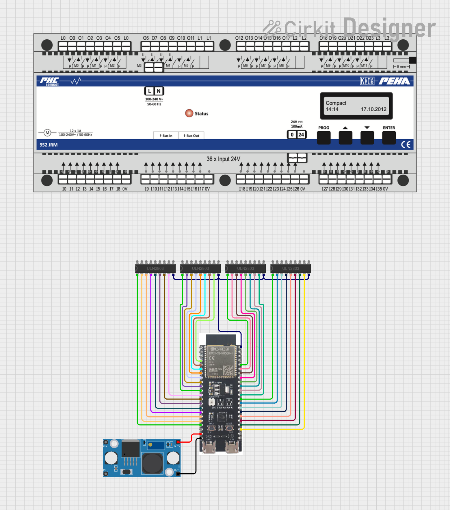 Open Project in Cirkit Designer
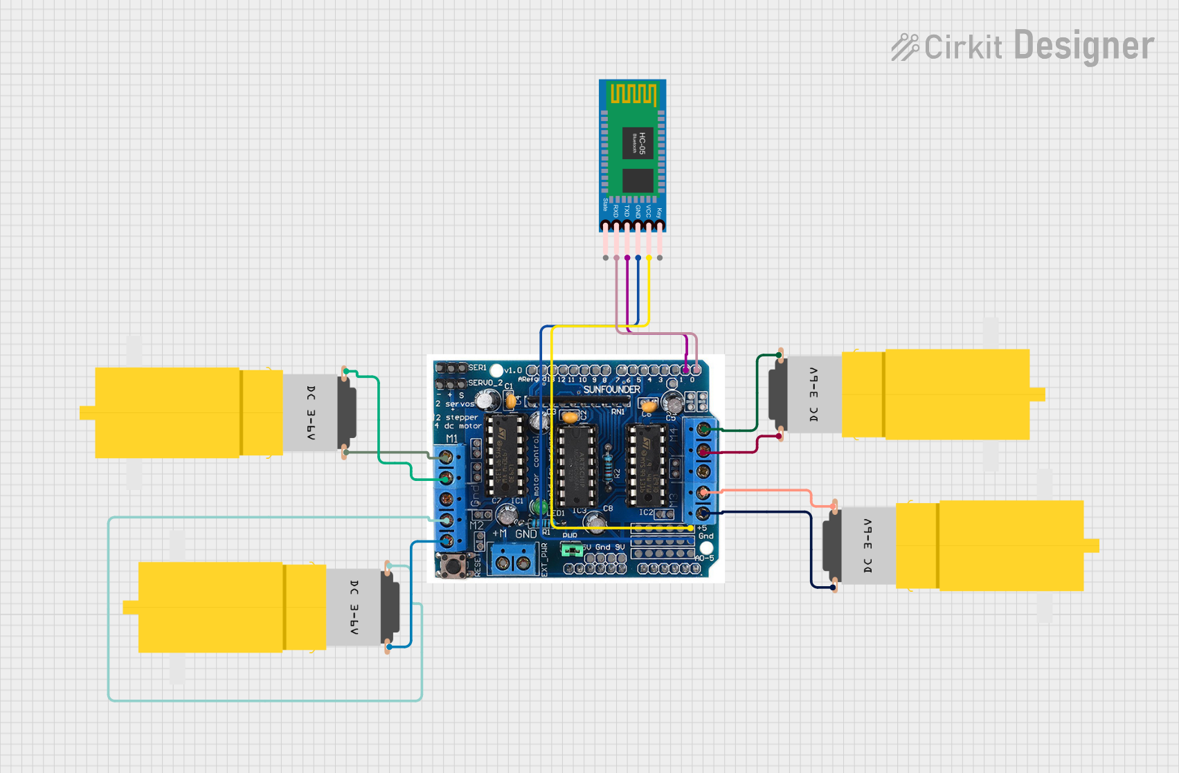 Open Project in Cirkit Designer
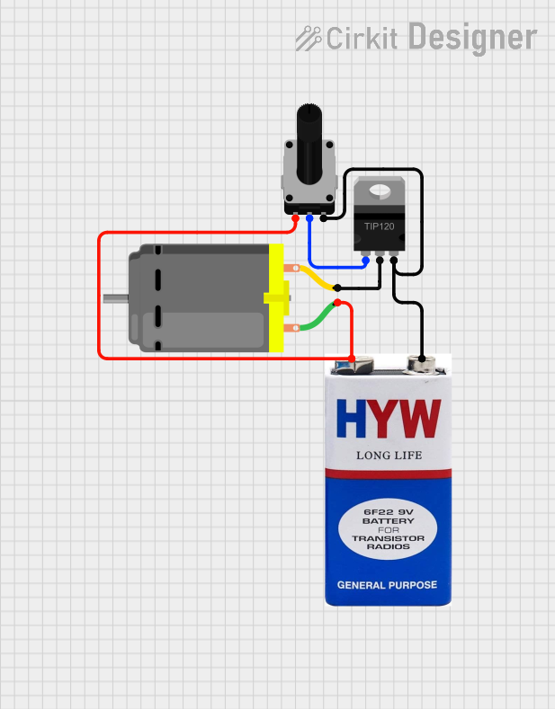 Open Project in Cirkit Designer
 Open Project in Cirkit Designer
Explore Projects Built with Darlington Driver
Open Project in Cirkit DesignerOpen Project in Cirkit DesignerOpen Project in Cirkit DesignerOpen Project in Cirkit DesignerTechnical Specifications
Below are the general technical specifications for a typical Darlington Driver (e.g., ULN2003A, a popular Darlington array IC):
Key Specifications
- Supply Voltage (Vcc): Up to 50V (varies by model)
- Output Current (per channel): Typically 500mA to 600mA
- Input Voltage (Logic High): 2.4V to 5V (TTL/CMOS compatible)
- Current Gain (hFE): 1000 to 10,000
- Number of Channels: 7 (for ULN2003A) or 8 (for ULN2803A)
- Integrated Freewheeling Diodes: Protects against back EMF from inductive loads
- Package Type: DIP, SOIC, or other IC packages
Pin Configuration and Descriptions
Below is the pinout for the ULN2003A Darlington Driver IC:
| Pin Number | Pin Name | Description |
|---|---|---|
| 1-7 | Input 1-7 | Logic-level inputs for each Darlington pair. Connect to microcontroller outputs. |
| 8 | GND | Ground pin. Connect to the circuit ground. |
| 9 | COM | Common pin for freewheeling diodes. Connect to the positive supply of the load. |
| 10-16 | Output 7-1 | Outputs for each Darlington pair. Connect to the load. |
Usage Instructions
How to Use the Component in a Circuit
- Power Supply: Ensure the Darlington Driver is powered within its specified voltage range. Connect the GND pin to the circuit ground.
- Inputs: Connect the input pins to the control signals from a microcontroller, such as an Arduino UNO. The input voltage should be within the logic-level range (e.g., 2.4V to 5V for TTL/CMOS).
- Outputs: Connect the output pins to the load (e.g., motor, relay, or LED array). Ensure the load current does not exceed the maximum output current rating.
- Freewheeling Diodes: If driving inductive loads (e.g., motors or relays), connect the COM pin to the positive supply of the load to utilize the internal freewheeling diodes for back EMF protection.
Example Circuit with Arduino UNO
Below is an example of using the ULN2003A Darlington Driver to control a 12V DC motor with an Arduino UNO:
Circuit Connections:
- Arduino Pin 3 → ULN2003A Input 1 (Pin 1)
- ULN2003A Output 1 (Pin 16) → Motor Positive Terminal
- Motor Negative Terminal → GND
- ULN2003A COM Pin (Pin 9) → 12V Motor Supply Positive
- ULN2003A GND Pin (Pin 8) → Arduino GND
Arduino Code:
// Example code to control a motor using ULN2003A and Arduino UNO

const int motorPin = 3; // Arduino pin connected to ULN2003A Input 1

void setup() {
  pinMode(motorPin, OUTPUT); // Set motor control pin as output
}

void loop() {
  digitalWrite(motorPin, HIGH); // Turn the motor ON
  delay(2000); // Keep the motor ON for 2 seconds
  digitalWrite(motorPin, LOW); // Turn the motor OFF
  delay(2000); // Keep the motor OFF for 2 seconds
}
Important Considerations and Best Practices
- Current Limitation: Ensure the total current drawn by all channels does not exceed the IC's maximum rating.
- Heat Dissipation: If driving high-current loads, consider adding a heatsink or ensuring proper ventilation to prevent overheating.
- Inductive Loads: Always connect the COM pin to the positive supply of the load to protect the IC from voltage spikes caused by back EMF.
- Unused Inputs: Tie unused input pins to ground to avoid floating inputs, which can cause erratic behavior.
Troubleshooting and FAQs
Common Issues and Solutions
Problem: The load is not turning on.
- Solution: Check the input signal voltage. Ensure it meets the logic-level requirements of the Darlington Driver.
- Solution: Verify the connections to the load and ensure the load is functional.
- Solution: Confirm that the COM pin is connected to the positive supply of the load.
Problem: The IC is overheating.
- Solution: Ensure the total current drawn by all channels does not exceed the IC's maximum rating.
- Solution: Add a heatsink or improve ventilation around the IC.
Problem: Erratic behavior or noise in the circuit.
- Solution: Tie unused input pins to ground to prevent floating inputs.
- Solution: Add decoupling capacitors near the power supply pins to reduce noise.
FAQs
Q: Can I use the Darlington Driver with a 3.3V microcontroller?
A: Yes, as long as the input voltage meets the logic-level requirements of the Darlington Driver. Check the datasheet for compatibility.Q: Can I drive multiple loads simultaneously?
A: Yes, but ensure the total current drawn by all loads does not exceed the IC's maximum current rating.Q: Do I need external diodes for inductive loads?
A: No, the Darlington Driver typically includes integrated freewheeling diodes for back EMF protection.
This concludes the documentation for the Darlington Driver.