How to Use pzemv4: Examples, Pinouts, and Specs
Introduction
The PZEM-004T V4 is a multifunctional energy meter designed for monitoring and managing electrical systems. It provides real-time measurements of key electrical parameters, including voltage, current, power, energy, frequency, and power factor. This compact and versatile module is widely used in applications such as home automation, industrial energy monitoring, and renewable energy systems.
Explore Projects Built with pzemv4


Explore Projects Built with pzemv4
Common Applications
- Home energy monitoring systems
- Industrial equipment power usage tracking
- Renewable energy systems (e.g., solar or wind power monitoring)
- Smart IoT-based energy management solutions
- Electrical system diagnostics and optimization
Technical Specifications
The following table outlines the key technical specifications of the PZEM-004T V4:
| Parameter | Specification |
|---|---|
| Voltage Range | 80V - 260V AC |
| Current Range | 0A - 100A (with external current transformer) |
| Power Range | 0W - 22kW |
| Energy Range | 0kWh - 9999kWh |
| Frequency Range | 45Hz - 65Hz |
| Power Factor Range | 0.00 - 1.00 |
| Communication Interface | UART (TTL level) |
| Baud Rate | 9600 bps |
| Operating Temperature | -10°C to 60°C |
| Dimensions | 48mm x 23mm x 22mm |
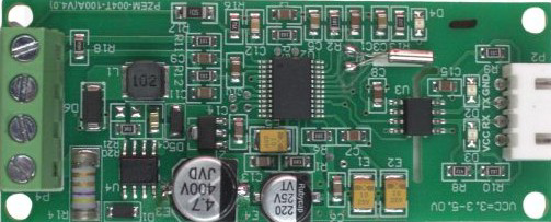
Pin Configuration
The PZEM-004T V4 has a 4-pin interface for communication and power. The pin configuration is as follows:
| Pin | Name | Description |
|---|---|---|
| 1 | VCC | Power supply input (5V DC) |
| 2 | GND | Ground |
| 3 | RX | UART Receive (connect to TX of microcontroller) |
| 4 | TX | UART Transmit (connect to RX of microcontroller) |
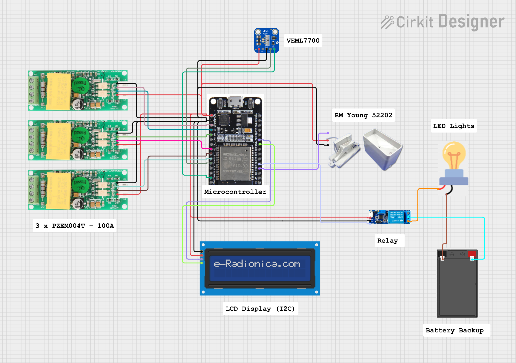
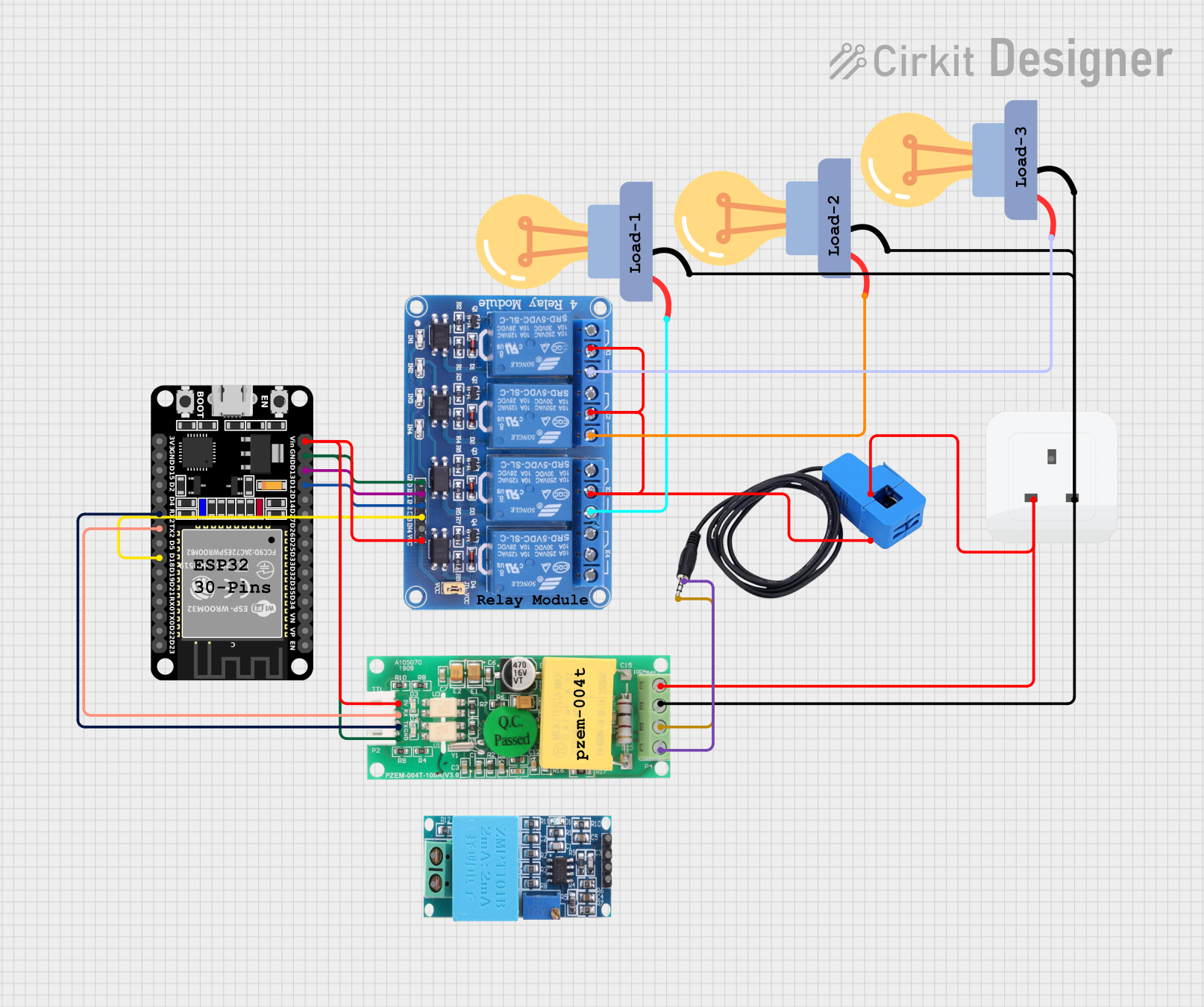
Usage Instructions
Connecting the PZEM-004T V4
- Power Supply: Connect the VCC pin to a 5V DC power source and the GND pin to ground.
- UART Communication: Connect the RX pin of the PZEM-004T V4 to the TX pin of your microcontroller (e.g., Arduino UNO) and the TX pin of the PZEM-004T V4 to the RX pin of the microcontroller.
- Current Transformer (CT): Attach the included current transformer to the PZEM-004T V4 and clamp it around the live wire of the AC circuit you want to monitor.
- AC Voltage Input: Connect the AC voltage input terminals of the PZEM-004T V4 to the live and neutral wires of the AC circuit.
Important Considerations
- Ensure that the current transformer is properly clamped around the live wire only. Clamping it around both live and neutral wires will result in incorrect readings.
- Do not exceed the specified voltage and current ranges to avoid damaging the module.
- Use proper insulation and safety precautions when working with high-voltage AC circuits.
- The module communicates using UART at a fixed baud rate of 9600 bps. Ensure your microcontroller is configured to match this baud rate.
Example Code for Arduino UNO
Below is an example Arduino sketch to interface with the PZEM-004T V4 and read its measurements:
#include <SoftwareSerial.h>

// Define RX and TX pins for SoftwareSerial
SoftwareSerial pzemSerial(10, 11); // RX = pin 10, TX = pin 11

// Include the PZEM library
#include <PZEM004Tv30.h>
PZEM004Tv30 pzem(&pzemSerial); // Initialize PZEM object with SoftwareSerial

void setup() {
  Serial.begin(9600); // Start Serial Monitor
  pzemSerial.begin(9600); // Start communication with PZEM-004T V4
  Serial.println("PZEM-004T V4 Energy Meter Example");
}

void loop() {
  // Read voltage
  float voltage = pzem.voltage();
  if (!isnan(voltage)) {
    Serial.print("Voltage: ");
    Serial.print(voltage);
    Serial.println(" V");
  } else {
    Serial.println("Error reading voltage!");
  }

  // Read current
  float current = pzem.current();
  if (!isnan(current)) {
    Serial.print("Current: ");
    Serial.print(current);
    Serial.println(" A");
  } else {
    Serial.println("Error reading current!");
  }

  // Read power
  float power = pzem.power();
  if (!isnan(power)) {
    Serial.print("Power: ");
    Serial.print(power);
    Serial.println(" W");
  } else {
    Serial.println("Error reading power!");
  }

  // Read energy
  float energy = pzem.energy();
  if (!isnan(energy)) {
    Serial.print("Energy: ");
    Serial.print(energy);
    Serial.println(" kWh");
  } else {
    Serial.println("Error reading energy!");
  }

  // Read frequency
  float frequency = pzem.frequency();
  if (!isnan(frequency)) {
    Serial.print("Frequency: ");
    Serial.print(frequency);
    Serial.println(" Hz");
  } else {
    Serial.println("Error reading frequency!");
  }

  // Read power factor
  float pf = pzem.pf();
  if (!isnan(pf)) {
    Serial.print("Power Factor: ");
    Serial.println(pf);
  } else {
    Serial.println("Error reading power factor!");
  }

  delay(2000); // Wait 2 seconds before the next reading
}
Notes on the Code
- The
PZEM004Tv30library is required to use this code. Install it via the Arduino Library Manager. - Adjust the RX and TX pin numbers in the
SoftwareSerialdeclaration to match your wiring. - Use the Serial Monitor (set to 9600 baud) to view the readings.
Troubleshooting and FAQs
Common Issues
No Data or Incorrect Readings:
- Ensure the current transformer is clamped around the live wire only.
- Verify that the AC voltage input terminals are securely connected to the live and neutral wires.
- Check the UART connections between the PZEM-004T V4 and the microcontroller.
Communication Errors:
- Confirm that the baud rate of the microcontroller matches the PZEM-004T V4 (9600 bps).
- Ensure the RX and TX pins are correctly connected (crossed: RX to TX and TX to RX).
Module Not Powering On:
- Verify that the VCC pin is receiving a stable 5V DC supply.
- Check for loose or damaged wires.
FAQs
Q: Can the PZEM-004T V4 measure DC voltage or current?
A: No, the PZEM-004T V4 is designed specifically for AC voltage and current measurements.
Q: Can I use multiple PZEM-004T V4 modules with one microcontroller?
A: Yes, you can use multiple modules by assigning each one a unique address using the PZEM library.
Q: What is the maximum distance for UART communication?
A: The maximum reliable distance for UART communication depends on the baud rate and cable quality, but it is typically limited to a few meters.
Q: How do I reset the energy reading to zero?
A: Use the pzem.resetEnergy() function in the PZEM library to reset the energy counter.
By following this documentation, you can effectively integrate the PZEM-004T V4 into your projects for accurate energy monitoring and management.