How to Use 7 segment: Examples, Pinouts, and Specs
Introduction
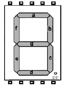
The 7-segment display (Manufacturer: IC, Part ID: IC 7 SEG) is an electronic display device designed to represent decimal numbers and some letters. It consists of seven individual LED segments arranged in a figure-eight pattern, which can be illuminated in various combinations to display digits from 0 to 9. Some alphanumeric characters can also be represented.
Explore Projects Built with 7 segment
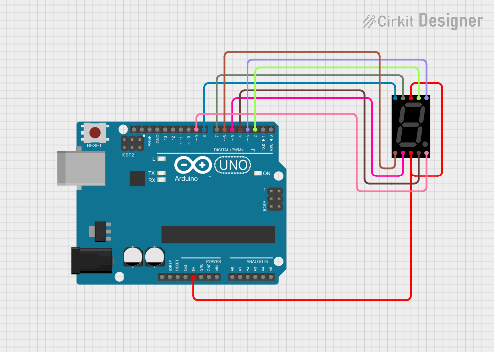
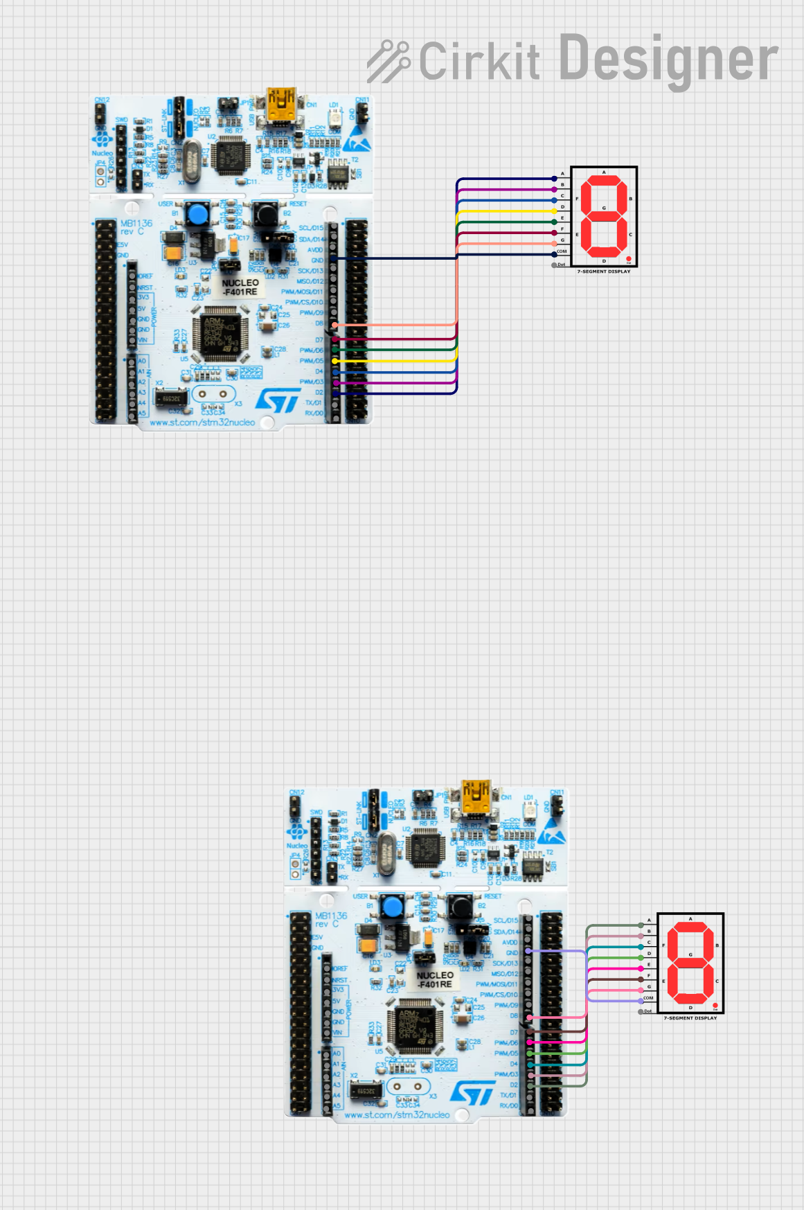
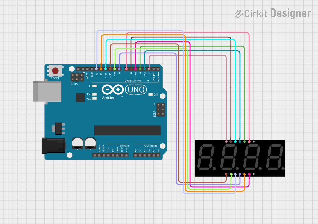
Explore Projects Built with 7 segment
Common Applications and Use Cases
- Digital clocks
- Calculators
- Electronic meters (e.g., voltmeters, ammeters)
- Home appliances (e.g., microwave ovens, washing machines)
- Embedded systems for numeric or limited alphanumeric displays
Technical Specifications
Key Technical Details
- Operating Voltage: Typically 2V to 3.5V per segment (depends on LED type)
- Forward Current: 10mA to 20mA per segment
- Power Consumption: Varies based on the number of active segments
- Display Type: Common Anode (CA) or Common Cathode (CC)
- Number of Segments: 7 segments + optional decimal point (DP)
- Viewing Angle: ~90° (varies by manufacturer)
- Dimensions: Varies (e.g., 0.56-inch, 1-inch digit height)
Pin Configuration and Descriptions
The pin configuration depends on whether the display is Common Anode (CA) or Common Cathode (CC). Below is a general pinout for a 7-segment display with 10 pins:
| Pin Number | Label | Description |
|---|---|---|
| 1 | a | Segment "a" control |
| 2 | b | Segment "b" control |
| 3 | c | Segment "c" control |
| 4 | Dp | Decimal point control |
| 5 | GND | Common Cathode (CC) or Common Anode (CA) |
| 6 | e | Segment "e" control |
| 7 | d | Segment "d" control |
| 8 | GND | Common Cathode (CC) or Common Anode (CA) |
| 9 | f | Segment "f" control |
| 10 | g | Segment "g" control |
Note: For Common Anode displays, the common pin (GND) is connected to the positive voltage supply, and segments are activated by grounding their respective pins. For Common Cathode displays, the common pin is connected to ground, and segments are activated by applying a positive voltage.
Usage Instructions
How to Use the Component in a Circuit
- Determine the Type: Identify whether your 7-segment display is Common Anode (CA) or Common Cathode (CC).
- Connect the Common Pin:
- For CA: Connect the common pin(s) to the positive voltage supply (e.g., 5V).
- For CC: Connect the common pin(s) to ground.
- Use Current-Limiting Resistors: Connect a resistor (typically 220Ω to 1kΩ) in series with each segment to limit the current and prevent damage to the LEDs.
- Control the Segments: Use a microcontroller (e.g., Arduino UNO) or other control circuitry to apply voltage to the appropriate segment pins to display the desired digit.
Important Considerations and Best Practices
- Resistor Selection: Always use appropriate resistors to limit current through each segment.
- Power Supply: Ensure the power supply voltage matches the operating voltage of the display.
- Driving the Display: For multiple displays, consider using a driver IC (e.g., MAX7219) to simplify control and reduce the number of required microcontroller pins.
- Brightness Control: Use Pulse Width Modulation (PWM) to adjust the brightness of the display if needed.
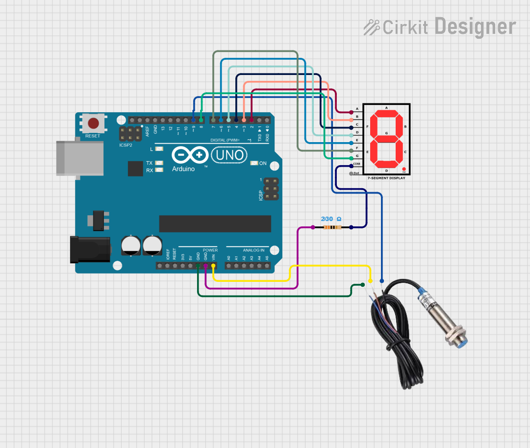
Example: Connecting to an Arduino UNO
Below is an example of how to connect a Common Cathode 7-segment display to an Arduino UNO to display the digit "3":
Circuit Connections
- Connect the common cathode pin to GND.
- Connect each segment pin (a, b, c, d, e, f, g) to Arduino digital pins via 220Ω resistors.
Arduino Code
// Define segment pins connected to Arduino
const int segmentPins[] = {2, 3, 4, 5, 6, 7, 8}; // a, b, c, d, e, f, g

// Segment states for displaying the digit "3"
// 1 = ON, 0 = OFF
const int digitThree[] = {1, 1, 1, 1, 0, 0, 1};

void setup() {
  // Set segment pins as outputs
  for (int i = 0; i < 7; i++) {
    pinMode(segmentPins[i], OUTPUT);
  }
}

void loop() {
  // Display the digit "3"
  for (int i = 0; i < 7; i++) {
    digitalWrite(segmentPins[i], digitThree[i]);
  }
  delay(1000); // Keep the digit displayed for 1 second
}
Note: Modify the digitThree array to display other digits by changing the segment states.
Troubleshooting and FAQs
Common Issues and Solutions
Segments Not Lighting Up:
- Check the connections and ensure the common pin is correctly connected (GND for CC, VCC for CA).
- Verify that current-limiting resistors are in place and of the correct value.
- Ensure the microcontroller pins are configured as outputs.
Incorrect Digits Displayed:
- Double-check the segment-to-pin mapping in your circuit and code.
- Verify the logic levels for your specific display type (CA or CC).
Dim or Uneven Brightness:
- Ensure all resistors are of the same value.
- Check the power supply voltage and current capacity.
Display Flickering:
- If using multiplexing, ensure the refresh rate is high enough (e.g., >60Hz).
- Check for loose connections or unstable power supply.
FAQs
Q: Can I control multiple 7-segment displays with an Arduino?
A: Yes, you can use multiplexing or a driver IC like the MAX7219 to control multiple displays with fewer pins.
Q: How do I display letters on a 7-segment display?
A: Some letters (e.g., A, b, C, d, E, F) can be displayed by illuminating specific segments. However, not all letters can be represented due to the limited segment arrangement.
Q: Can I use a 7-segment display without a microcontroller?
A: Yes, you can use switches, logic gates, or a BCD-to-7-segment decoder IC (e.g., 74LS47) to control the display without a microcontroller.