How to Use Smart Shunt: Examples, Pinouts, and Specs
Introduction
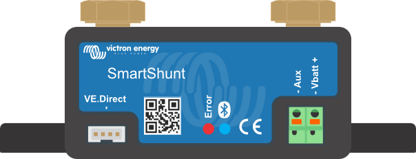
The Smart Shunt by Victron Energy is a high-precision resistor designed for use in battery management systems (BMS). It measures the current flow by detecting the voltage drop across the shunt, enabling real-time monitoring of battery performance. This data is crucial for determining the state of charge (SoC), state of health (SoH), and other key battery parameters. The Smart Shunt is available in multiple current ratings: 300A, 500A, 1000A, and 2000A, making it suitable for a wide range of applications.
Explore Projects Built with Smart Shunt
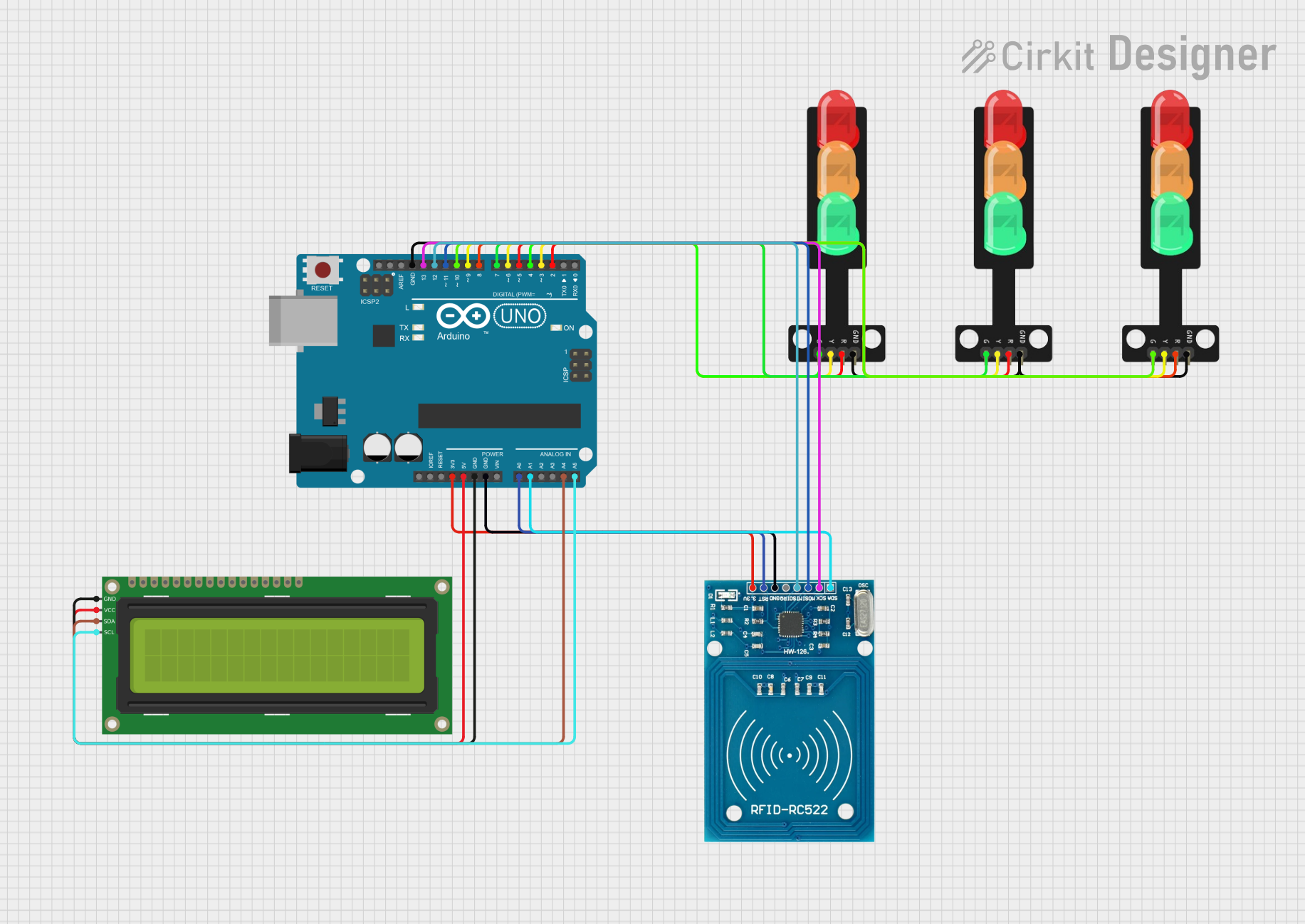


Explore Projects Built with Smart Shunt
Common Applications
- Battery monitoring in renewable energy systems (e.g., solar, wind)
- Marine and RV battery systems
- Industrial battery banks
- Electric vehicles (EVs) and energy storage systems
- Off-grid power systems
Technical Specifications
General Specifications
| Parameter | Value |
|---|---|
| Manufacturer | Victron Energy |
| Part IDs | 300A, 500A, 1000A, 2000A |
| Voltage Range | 6.5V to 70V DC |
| Current Ratings | 300A, 500A, 1000A, 2000A |
| Communication Interface | Bluetooth, VE.Direct |
| Accuracy | ±0.5% |
| Power Consumption | < 1mA |
| Operating Temperature | -40°C to +60°C |
| Dimensions | Varies by model |
Pin Configuration and Descriptions
The Smart Shunt has a simple terminal configuration for easy integration into battery systems. Below is the pin/terminal description:
| Terminal Name | Description |
|---|---|
| B- | Connects to the negative terminal of the battery. |
| P- | Connects to the negative terminal of the load or charger. |
| VE.Direct | Communication port for connecting to Victron devices or monitoring systems. |
| Bluetooth | Wireless communication for real-time monitoring via a smartphone app. |
Usage Instructions
How to Use the Smart Shunt in a Circuit
Placement in the Circuit:
- The Smart Shunt must be installed on the negative side of the battery system.
- Connect the B- terminal to the battery's negative terminal.
- Connect the P- terminal to the negative terminal of the load or charger.
Power Supply:
- Ensure the battery voltage is within the supported range (6.5V to 70V DC).
- The shunt is powered directly by the battery, so no external power source is required.
Communication Setup:
- Use the VE.Direct port to connect the shunt to a Victron GX device or other compatible systems.
- Alternatively, pair the shunt with a smartphone via Bluetooth using the VictronConnect app.
Monitoring:
- Open the VictronConnect app to view real-time data, including current, voltage, SoC, and SoH.
- Configure alarms and thresholds for battery performance monitoring.
Important Considerations and Best Practices
- Current Rating: Select a Smart Shunt model with a current rating higher than the maximum expected current in your system.
- Cable Sizing: Use appropriately sized cables to minimize resistance and ensure accurate measurements.
- Secure Connections: Tighten all connections to avoid loose terminals, which can lead to inaccurate readings or damage.
- Environmental Protection: Install the shunt in a dry, well-ventilated area to protect it from moisture and extreme temperatures.
- Firmware Updates: Regularly check for firmware updates via the VictronConnect app to ensure optimal performance.
Example Arduino Integration
While the Smart Shunt is not directly designed for Arduino, it can be interfaced using the VE.Direct protocol. Below is an example of how to read data from the Smart Shunt using an Arduino and a VE.Direct to UART adapter.
#include <SoftwareSerial.h>

// Define RX and TX pins for VE.Direct communication
SoftwareSerial veDirectSerial(10, 11); // RX = pin 10, TX = pin 11

void setup() {
  Serial.begin(9600); // Initialize serial monitor
  veDirectSerial.begin(19200); // Initialize VE.Direct communication

  Serial.println("Smart Shunt Data Logger");
}

void loop() {
  // Check if data is available from the Smart Shunt
  if (veDirectSerial.available()) {
    String data = ""; // Initialize a string to store incoming data

    // Read data from the VE.Direct port
    while (veDirectSerial.available()) {
      char c = veDirectSerial.read();
      data += c;

      // Break if a newline character is detected
      if (c == '\n') {
        break;
      }
    }

    // Print the received data to the serial monitor
    Serial.print("Received: ");
    Serial.println(data);
  }
}
Note: The VE.Direct protocol requires parsing specific data fields. Refer to the Victron Energy VE.Direct protocol documentation for detailed information.
Troubleshooting and FAQs
Common Issues and Solutions
| Issue | Possible Cause | Solution |
|---|---|---|
| No data in the VictronConnect app | Bluetooth not paired or out of range | Ensure the smartphone is within range and pair the device via Bluetooth. |
| Inaccurate current readings | Loose or incorrect connections | Verify all connections are secure and correctly installed. |
| VE.Direct communication failure | Incorrect wiring or baud rate mismatch | Check the VE.Direct cable and ensure the baud rate is set to 19200. |
| High power consumption | Faulty installation or damaged shunt | Inspect the shunt for damage and ensure proper installation. |
FAQs
Can the Smart Shunt be used with a 24V battery system?
- Yes, the Smart Shunt supports battery voltages from 6.5V to 70V DC, including 12V, 24V, and 48V systems.
What is the maximum cable length for VE.Direct communication?
- The recommended maximum cable length is 10 meters to ensure reliable communication.
Can I use the Smart Shunt without a Victron GX device?
- Yes, you can monitor data via the VictronConnect app using Bluetooth.
How do I update the firmware?
- Use the VictronConnect app to check for and install firmware updates over Bluetooth.
By following this documentation, users can effectively integrate and utilize the Victron Energy Smart Shunt in their battery management systems.