
How to Use BLDC Motor: Examples, Pinouts, and Specs
 Design with BLDC Motor in Cirkit Designer
Introduction
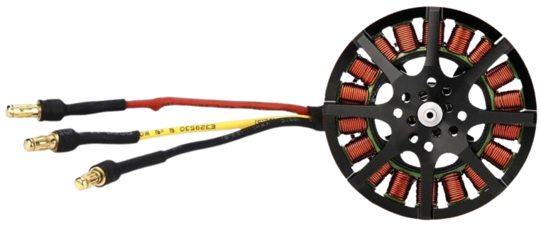
A Brushless DC (BLDC) Motor is an electric motor that operates without brushes, using electronic commutation instead of mechanical commutation. This design eliminates the wear and tear associated with brushes, resulting in higher efficiency, reliability, and a longer lifespan. BLDC motors are known for their precise speed and torque control, making them ideal for a wide range of applications.
Explore Projects Built with BLDC Motor
 Open Project in Cirkit Designer
 Open Project in Cirkit Designer
 Open Project in Cirkit Designer
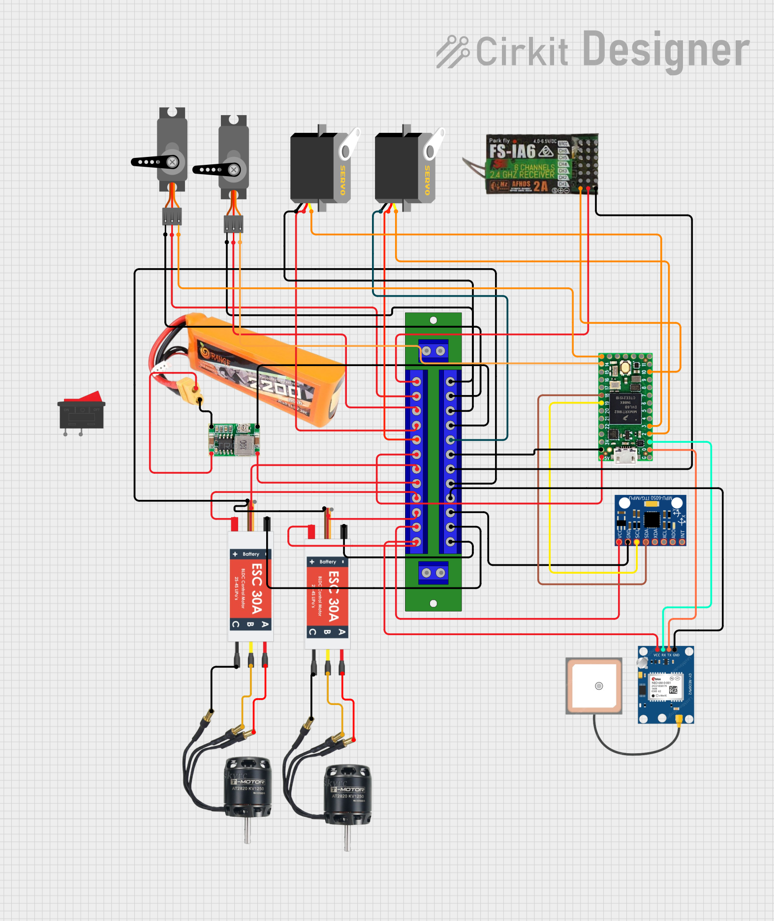 Open Project in Cirkit Designer
Explore Projects Built with BLDC Motor
Open Project in Cirkit DesignerOpen Project in Cirkit DesignerOpen Project in Cirkit DesignerOpen Project in Cirkit DesignerCommon Applications and Use Cases
- Robotics: For precise motion control and high torque requirements.
- Electric Vehicles: Used in propulsion systems for their efficiency and durability.
- Industrial Automation: Drives for conveyor belts, pumps, and fans.
- Drones: Lightweight and efficient motors for flight control.
- HVAC Systems: Energy-efficient motors for compressors and fans.
Technical Specifications
Below are the general technical specifications for a typical BLDC motor. Note that specific values may vary depending on the motor model and manufacturer.
Key Technical Details
| Parameter | Value/Range |
|---|---|
| Operating Voltage | 12V - 48V (common range) |
| Rated Current | 1A - 50A (depending on size) |
| Power Output | 10W - 10kW |
| Speed Range | 1,000 - 20,000 RPM |
| Torque Range | 0.1 Nm - 10 Nm |
| Efficiency | Up to 95% |
| Commutation Type | Electronic (via ESC) |
| Number of Poles | 2 - 14 |
Pin Configuration and Descriptions
BLDC motors typically have three main wires for phase connections and additional wires for sensors (if applicable). Below is a general pinout description:
Motor Phase Wires
| Wire Color | Description |
|---|---|
| Red | Phase A |
| Yellow | Phase B |
| Blue | Phase C |
Hall Sensor Wires (if applicable)
| Wire Color | Description |
|---|---|
| Black | Ground (GND) |
| Red | Power Supply (e.g., 5V) |
| Green | Hall Sensor Signal A |
| Yellow | Hall Sensor Signal B |
| Blue | Hall Sensor Signal C |
Usage Instructions
How to Use the BLDC Motor in a Circuit
Connect the Motor to an ESC (Electronic Speed Controller):
- The three-phase wires (Red, Yellow, Blue) of the motor should be connected to the corresponding output terminals of the ESC.
- Ensure the ESC is compatible with the motor's voltage and current ratings.
Power the ESC:
- Provide a suitable DC power supply to the ESC, matching the motor's operating voltage range.
Control the Motor:
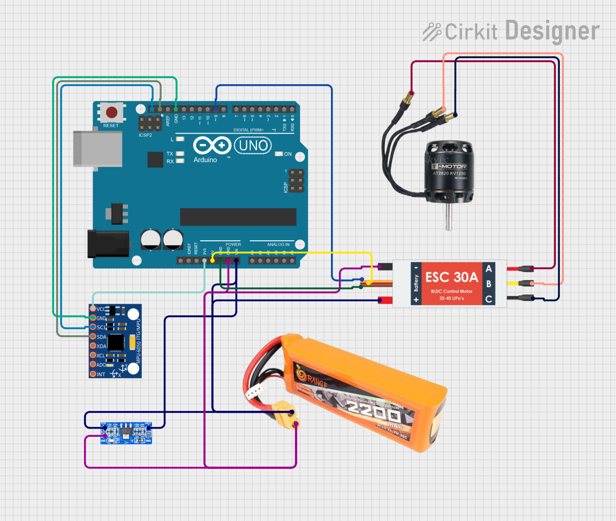
- Use a microcontroller (e.g., Arduino UNO) or a PWM signal generator to send control signals to the ESC.
- The ESC interprets the PWM signals to adjust the motor's speed and direction.
Optional: Connect Hall Sensors:
- If the motor has Hall sensors, connect the sensor wires to the microcontroller or ESC for precise position feedback.
Important Considerations and Best Practices
- Cooling: Ensure proper cooling for high-power motors to prevent overheating.
- ESC Selection: Choose an ESC with a current rating higher than the motor's maximum current draw.
- Power Supply: Use a stable and adequately rated power supply to avoid voltage drops.
- Wiring: Keep wires short and secure to minimize electrical noise and losses.
- Startup Sequence: Some BLDC motors require a specific startup sequence for proper operation.
Example: Controlling a BLDC Motor with Arduino UNO
Below is an example of Arduino code to control a BLDC motor using an ESC:
// Example: Controlling a BLDC Motor with Arduino UNO
// This code generates a PWM signal to control the ESC and motor speed.

#include <Servo.h> // Include the Servo library for generating PWM signals

Servo esc; // Create a Servo object to control the ESC

void setup() {
  esc.attach(9); // Attach the ESC signal wire to pin 9 on the Arduino
  esc.writeMicroseconds(1000); // Send minimum throttle signal to initialize ESC
  delay(2000); // Wait for the ESC to arm (check ESC manual for arming time)
}

void loop() {
  // Gradually increase motor speed
  for (int speed = 1000; speed <= 2000; speed += 10) {
    esc.writeMicroseconds(speed); // Send PWM signal to ESC
    delay(50); // Wait for 50ms before increasing speed
  }

  delay(2000); // Run at full speed for 2 seconds

  // Gradually decrease motor speed
  for (int speed = 2000; speed >= 1000; speed -= 10) {
    esc.writeMicroseconds(speed); // Send PWM signal to ESC
    delay(50); // Wait for 50ms before decreasing speed
  }

  delay(2000); // Wait for 2 seconds before repeating the loop
}
Troubleshooting and FAQs
Common Issues and Solutions
Motor Does Not Spin:
- Cause: Incorrect wiring or ESC not armed.
- Solution: Double-check all connections and ensure the ESC is properly armed.
Motor Spins in the Wrong Direction:
- Cause: Phase wires are connected incorrectly.
- Solution: Swap any two of the three-phase wires to reverse the motor's direction.
Motor Overheats:
- Cause: Overloading or insufficient cooling.
- Solution: Reduce the load, improve cooling, or use a higher-rated motor.
ESC Beeps Continuously:
- Cause: ESC is not receiving a valid PWM signal.
- Solution: Verify the microcontroller code and ensure the signal wire is connected correctly.
Jerky or Noisy Operation:
- Cause: Electrical noise or incorrect commutation.
- Solution: Check for loose connections, use shielded cables, and ensure the ESC is compatible with the motor.
FAQs
Q: Can I run a BLDC motor without an ESC?
A: No, an ESC is required to electronically commutate the motor and control its speed.Q: How do I select the right BLDC motor for my application?
A: Consider the required torque, speed, voltage, and current ratings based on your application's needs.Q: Can I use a BLDC motor with a battery?
A: Yes, as long as the battery voltage matches the motor and ESC requirements.Q: What is the advantage of using Hall sensors?
A: Hall sensors provide precise position feedback, enabling smoother operation and better control at low speeds.