Cirkit Designer
Your all-in-one circuit design IDE
Home /
Component Documentation
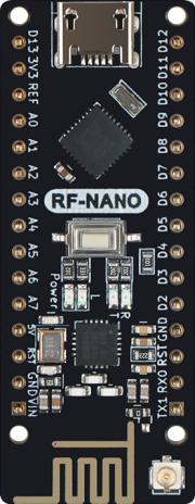
How to Use LGT_RF_NANO: Examples, Pinouts, and Specs
Introduction
The LGT_RF_NANO is a versatile microcontroller board developed by Makefun, featuring the LGT8F328P chip. This board is similar to the Arduino Nano but comes with enhanced capabilities, including RF communication. It is designed for a wide range of applications, from simple DIY projects to more complex IoT systems.
Explore Projects Built with LGT_RF_NANO
Arduino Nano-Based GPS Tracker with GSM and LoRa Communication

This circuit features an Arduino Nano microcontroller interfaced with an RFM95 LoRa transceiver module for long-range communication, a SIM800L GSM module for cellular connectivity, and a GPS NEO 6M module for location tracking. The Arduino Nano also connects to an inductive sensor for proximity or metal detection. The circuit is designed for applications requiring wireless communication, location tracking, and proximity sensing, with the Arduino Nano serving as the central processing unit.
Arduino Nano and RFM95 LoRa Transceiver with Inductor for Wireless Communication
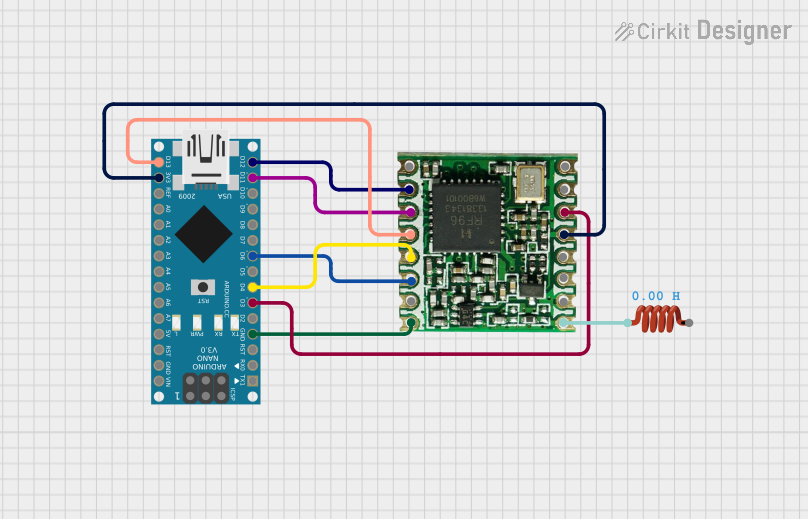
This circuit integrates an Arduino Nano with an RFM95 LoRa module for wireless communication. The Arduino Nano controls the RFM95 via SPI and digital I/O pins, while an inductor is connected to the antenna pin of the RFM95 to enhance signal transmission.
Arduino Nano Battery-Powered RF Transmitter with Arcade Button
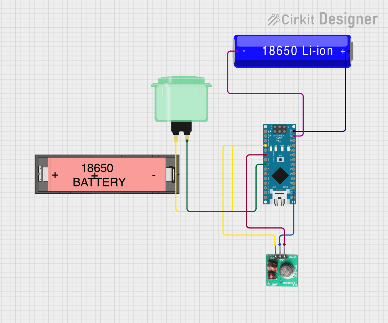
This circuit consists of an Arduino Nano microcontroller connected to an RF transmitter module and a green arcade button. The Arduino Nano is powered by a 18650 Li-ion battery and controls the RF module to transmit data when the arcade button is pressed.
Arduino Nano RP2040 Connect Wireless Transmitter with nRF24L01 and Battery Power
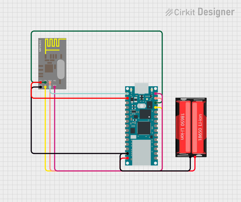
This circuit consists of an Arduino Nano RP2040 Connect microcontroller interfaced with an nRF24L01 wireless transceiver module, powered by a 18650 Li-Ion battery. The Arduino is programmed to transmit data wirelessly at regular intervals using the nRF24L01 module.
Explore Projects Built with LGT_RF_NANO
Arduino Nano-Based GPS Tracker with GSM and LoRa Communication
This circuit features an Arduino Nano microcontroller interfaced with an RFM95 LoRa transceiver module for long-range communication, a SIM800L GSM module for cellular connectivity, and a GPS NEO 6M module for location tracking. The Arduino Nano also connects to an inductive sensor for proximity or metal detection. The circuit is designed for applications requiring wireless communication, location tracking, and proximity sensing, with the Arduino Nano serving as the central processing unit.
Arduino Nano and RFM95 LoRa Transceiver with Inductor for Wireless Communication
This circuit integrates an Arduino Nano with an RFM95 LoRa module for wireless communication. The Arduino Nano controls the RFM95 via SPI and digital I/O pins, while an inductor is connected to the antenna pin of the RFM95 to enhance signal transmission.
Arduino Nano Battery-Powered RF Transmitter with Arcade Button
This circuit consists of an Arduino Nano microcontroller connected to an RF transmitter module and a green arcade button. The Arduino Nano is powered by a 18650 Li-ion battery and controls the RF module to transmit data when the arcade button is pressed.
Arduino Nano RP2040 Connect Wireless Transmitter with nRF24L01 and Battery Power
This circuit consists of an Arduino Nano RP2040 Connect microcontroller interfaced with an nRF24L01 wireless transceiver module, powered by a 18650 Li-Ion battery. The Arduino is programmed to transmit data wirelessly at regular intervals using the nRF24L01 module.
Common Applications and Use Cases
- Wireless Sensor Networks: Ideal for creating networks of sensors that communicate wirelessly.
- Home Automation: Can be used to control home appliances and systems remotely.
- Robotics: Suitable for controlling robots and other automated systems.
- IoT Projects: Perfect for Internet of Things applications requiring wireless communication.
Technical Specifications
Key Technical Details
| Specification | Value |
|---|---|
| Microcontroller | LGT8F328P |
| Operating Voltage | 5V |
| Input Voltage | 7-12V |
| Digital I/O Pins | 14 (of which 6 provide PWM) |
| Analog Input Pins | 8 |
| Flash Memory | 32 KB (LGT8F328P) |
| SRAM | 2 KB |
| EEPROM | 1 KB |
| Clock Speed | 16 MHz |
| RF Communication | Integrated RF module |
Pin Configuration and Descriptions
| Pin Number | Pin Name | Description |
|---|---|---|
| 1 | D0/RX | Digital I/O, UART RX |
| 2 | D1/TX | Digital I/O, UART TX |
| 3 | D2 | Digital I/O |
| 4 | D3 | Digital I/O, PWM |
| 5 | D4 | Digital I/O |
| 6 | D5 | Digital I/O, PWM |
| 7 | D6 | Digital I/O, PWM |
| 8 | D7 | Digital I/O |
| 9 | D8 | Digital I/O |
| 10 | D9 | Digital I/O, PWM |
| 11 | D10 | Digital I/O, PWM |
| 12 | D11 | Digital I/O, SPI MOSI |
| 13 | D12 | Digital I/O, SPI MISO |
| 14 | D13 | Digital I/O, SPI SCK |
| 15 | A0 | Analog Input |
| 16 | A1 | Analog Input |
| 17 | A2 | Analog Input |
| 18 | A3 | Analog Input |
| 19 | A4 | Analog Input, I2C SDA |
| 20 | A5 | Analog Input, I2C SCL |
| 21 | A6 | Analog Input |
| 22 | A7 | Analog Input |
| 23 | GND | Ground |
| 24 | 5V | 5V Power Supply |
| 25 | 3.3V | 3.3V Power Supply |
| 26 | VIN | Input Voltage (7-12V) |
| 27 | RST | Reset |
| 28 | RF_TX | RF Transmit |
| 29 | RF_RX | RF Receive |
Usage Instructions
How to Use the Component in a Circuit
Powering the Board:
- Connect the VIN pin to a 7-12V power source, or use the USB connection for 5V power.
- Ensure the GND pin is connected to the ground of your power source.
Connecting Digital and Analog I/O:
- Use the digital pins (D0-D13) for digital input/output operations.
- Use the analog pins (A0-A7) for analog input operations.
RF Communication:
- Connect the RF_TX and RF_RX pins to the corresponding RF module pins for wireless communication.
Important Considerations and Best Practices
- Power Supply: Ensure the power supply voltage is within the specified range to avoid damaging the board.
- Pin Usage: Avoid using the same pin for multiple functions simultaneously to prevent conflicts.
- RF Communication: Ensure proper antenna placement and orientation for optimal RF performance.
Example Code
Here is an example code to demonstrate basic usage of the LGT_RF_NANO with an Arduino UNO for RF communication:
#include <SPI.h>
#include <RF24.h>

// Define the RF24 object with CE and CSN pins
RF24 radio(9, 10);

const byte address[6] = "00001"; // Define the address

void setup() {
  Serial.begin(9600);
  radio.begin();
  radio.openWritingPipe(address);
  radio.setPALevel(RF24_PA_MIN);
  radio.stopListening();
}

void loop() {
  const char text[] = "Hello World";
  radio.write(&text, sizeof(text));
  Serial.println("Sent: Hello World");
  delay(1000);
}
Troubleshooting and FAQs
Common Issues Users Might Face
Board Not Powering On:
- Solution: Check the power supply connections and ensure the voltage is within the specified range.
RF Communication Not Working:
- Solution: Verify the RF module connections and ensure the correct pins are used. Check the antenna placement.
Digital/Analog Pins Not Responding:
- Solution: Ensure the pins are not being used for multiple functions simultaneously. Check the code for pin conflicts.
Solutions and Tips for Troubleshooting
- Check Connections: Always double-check your wiring and connections.
- Use Serial Monitor: Utilize the Serial Monitor for debugging and checking the status of your code.
- Consult Datasheets: Refer to the LGT8F328P datasheet for detailed information on pin functions and electrical characteristics.
By following this documentation, users can effectively utilize the LGT_RF_NANO in their projects, leveraging its enhanced features for a wide range of applications.