Cirkit Designer Logo
Cirkit Designer
Your all-in-one circuit design IDE
Home / 
Component Documentation

How to Use accelerometer: Examples, Pinouts, and Specs

Image of accelerometer
Cirkit Designer LogoDesign with accelerometer in Cirkit Designer

Introduction

An accelerometer is a sensor that measures acceleration forces, which can be static (like gravity) or dynamic (caused by motion or vibration). These sensors are widely used in applications such as motion detection, orientation sensing, vibration monitoring, and gesture recognition. Common use cases include smartphones, fitness trackers, drones, robotics, and automotive systems.

Explore Projects Built with accelerometer

Use Cirkit Designer to design, explore, and prototype these projects online. Some projects support real-time simulation. Click "Open Project" to start designing instantly!
Arduino Nano and ADXL345 Accelerometer Interface
Image of Interfacing ADXL345 with Nano: A project utilizing accelerometer in a practical application
This circuit features an Arduino Nano interfaced with an ADXL345 accelerometer for measuring acceleration. The Arduino provides power and I2C communication to the accelerometer, enabling it to capture and process motion-related data.
Cirkit Designer LogoOpen Project in Cirkit Designer
Arduino UNO-Based Impact Detection and GPS Tracking System with GSM Communication
Image of smart helmet: A project utilizing accelerometer in a practical application
This circuit features an Arduino UNO interfaced with an ADXXL335 accelerometer, a Neo 6M GPS module, and a Sim800l GSM module. The Arduino collects acceleration data and GPS coordinates, and can send SMS alerts or make calls via the GSM module in case of a detected impact or upon receiving a specific SMS command. The system is designed for applications such as vehicle tracking and accident detection.
Cirkit Designer LogoOpen Project in Cirkit Designer
Arduino UNO-Based Accident Detection and Emergency Alert System with GPS and GSM
Image of iot tracker: A project utilizing accelerometer in a practical application
This circuit features an Arduino UNO microcontroller interfaced with an ADXXL335 accelerometer, a Neo 6M GPS module, and a Sim800l GSM module. The accelerometer's outputs are connected to the Arduino's analog inputs to detect motion, while the GPS module communicates with the Arduino via serial connection to provide location data. The Sim800l GSM module is also connected to the Arduino through serial communication, enabling the system to make calls and send SMS alerts with GPS coordinates in case of detected impacts or emergencies.
Cirkit Designer LogoOpen Project in Cirkit Designer
Arduino Mega 2560-Based Sensor Data Logger with ESP32-CAM and LCD Interface
Image of DA_Schema: A project utilizing accelerometer in a practical application
This is a multifunctional sensor system with visual feedback and control interfaces. It utilizes an Arduino Mega 2560 to process data from an accelerometer, ultrasonic sensor, and camera module, and displays information on an LCD screen. User inputs can be provided through toggle and DIP switches, while LEDs indicate system status.
Cirkit Designer LogoOpen Project in Cirkit Designer

Explore Projects Built with accelerometer

Use Cirkit Designer to design, explore, and prototype these projects online. Some projects support real-time simulation. Click "Open Project" to start designing instantly!
Image of Interfacing ADXL345 with Nano: A project utilizing accelerometer in a practical application
Arduino Nano and ADXL345 Accelerometer Interface
This circuit features an Arduino Nano interfaced with an ADXL345 accelerometer for measuring acceleration. The Arduino provides power and I2C communication to the accelerometer, enabling it to capture and process motion-related data.
Cirkit Designer LogoOpen Project in Cirkit Designer
Image of smart helmet: A project utilizing accelerometer in a practical application
Arduino UNO-Based Impact Detection and GPS Tracking System with GSM Communication
This circuit features an Arduino UNO interfaced with an ADXXL335 accelerometer, a Neo 6M GPS module, and a Sim800l GSM module. The Arduino collects acceleration data and GPS coordinates, and can send SMS alerts or make calls via the GSM module in case of a detected impact or upon receiving a specific SMS command. The system is designed for applications such as vehicle tracking and accident detection.
Cirkit Designer LogoOpen Project in Cirkit Designer
Image of iot tracker: A project utilizing accelerometer in a practical application
Arduino UNO-Based Accident Detection and Emergency Alert System with GPS and GSM
This circuit features an Arduino UNO microcontroller interfaced with an ADXXL335 accelerometer, a Neo 6M GPS module, and a Sim800l GSM module. The accelerometer's outputs are connected to the Arduino's analog inputs to detect motion, while the GPS module communicates with the Arduino via serial connection to provide location data. The Sim800l GSM module is also connected to the Arduino through serial communication, enabling the system to make calls and send SMS alerts with GPS coordinates in case of detected impacts or emergencies.
Cirkit Designer LogoOpen Project in Cirkit Designer
Image of DA_Schema: A project utilizing accelerometer in a practical application
Arduino Mega 2560-Based Sensor Data Logger with ESP32-CAM and LCD Interface
This is a multifunctional sensor system with visual feedback and control interfaces. It utilizes an Arduino Mega 2560 to process data from an accelerometer, ultrasonic sensor, and camera module, and displays information on an LCD screen. User inputs can be provided through toggle and DIP switches, while LEDs indicate system status.
Cirkit Designer LogoOpen Project in Cirkit Designer

Technical Specifications

Below are the general technical specifications for a typical 3-axis accelerometer (e.g., ADXL345 or MPU6050):

  • Operating Voltage: 3.3V to 5V
  • Measurement Range: ±2g, ±4g, ±8g, ±16g (configurable)
  • Sensitivity: Varies based on range (e.g., 256 LSB/g for ±16g)
  • Communication Interface: I2C or SPI
  • Power Consumption: ~0.1 mA in active mode, ~10 µA in sleep mode
  • Operating Temperature: -40°C to +85°C
  • Axes: 3 (X, Y, Z)

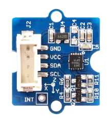
Pin Configuration and Descriptions

Below is the pinout for a common accelerometer module (e.g., MPU6050):

Pin Name Description
1 VCC Power supply input (3.3V or 5V, depending on the module).
2 GND Ground connection.
3 SCL Serial Clock Line for I2C communication.
4 SDA Serial Data Line for I2C communication.
5 INT Interrupt pin, used to signal events like data availability (optional).
6 AD0/CS Address selection for I2C (AD0) or Chip Select for SPI (CS), depending on mode.
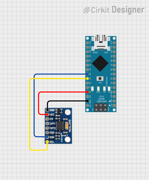
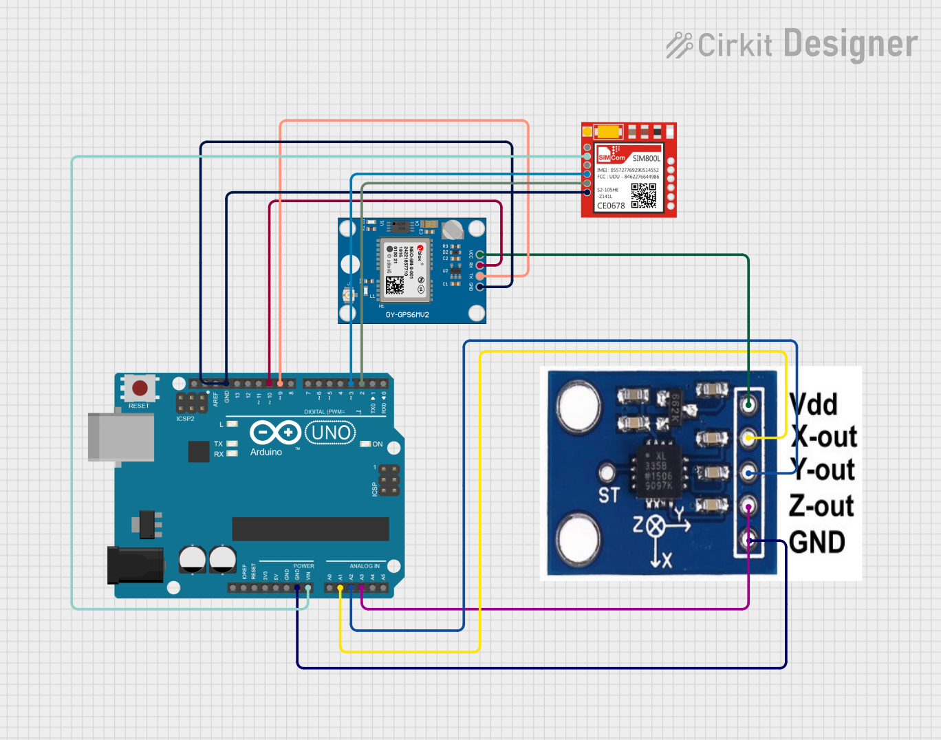
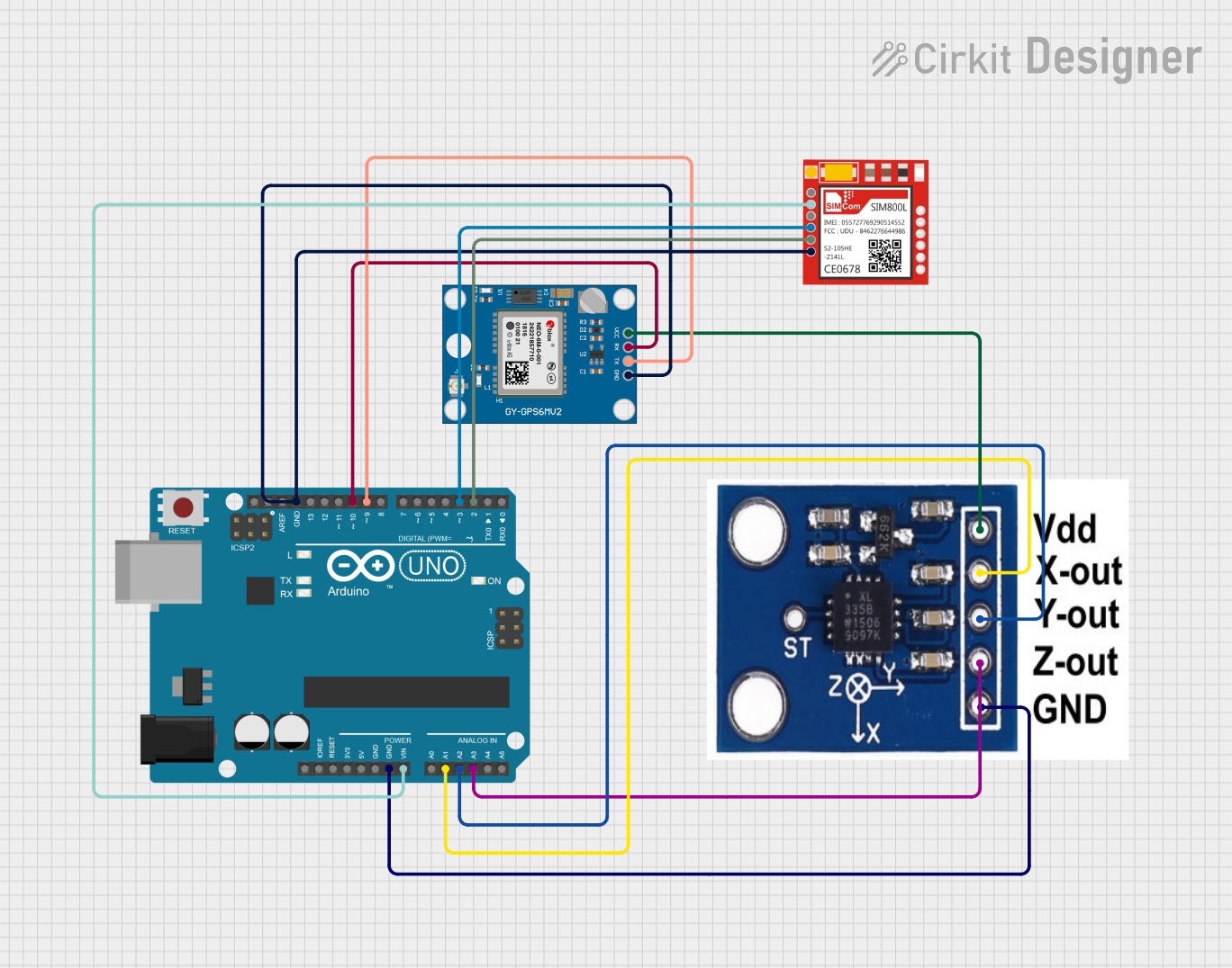
Usage Instructions

How to Use the Accelerometer in a Circuit

  1. Power the Module: Connect the VCC pin to a 3.3V or 5V power source and GND to ground.
  2. Connect Communication Lines:
    • For I2C: Connect the SDA and SCL pins to the corresponding pins on your microcontroller (e.g., Arduino UNO).
    • For SPI: Connect the CS, MOSI, MISO, and SCK pins as per your microcontroller's SPI configuration.
  3. Pull-Up Resistors: If using I2C, ensure pull-up resistors (typically 4.7kΩ) are connected to the SDA and SCL lines.
  4. Configure the Sensor: Use the appropriate library or code to initialize the accelerometer and set the desired measurement range and sensitivity.
  5. Read Data: Continuously read acceleration values from the X, Y, and Z axes.

Important Considerations and Best Practices

  • Power Supply: Ensure the module's operating voltage matches your microcontroller's logic level.
  • Noise Filtering: Use software filtering or hardware capacitors to reduce noise in the readings.
  • Mounting: Secure the accelerometer module firmly to avoid false readings caused by vibrations.
  • Orientation: Be aware of the sensor's orientation when interpreting acceleration data.

Example Code for Arduino UNO

Below is an example of how to use an MPU6050 accelerometer with an Arduino UNO via I2C:

#include <Wire.h>
#include <Adafruit_MPU6050.h>
#include <Adafruit_Sensor.h>

// Create an MPU6050 object
Adafruit_MPU6050 mpu;

void setup() {
  Serial.begin(115200);
  while (!Serial) {
    delay(10); // Wait for Serial Monitor to open
  }

  // Initialize I2C communication
  if (!mpu.begin()) {
    Serial.println("Failed to find MPU6050 chip. Check connections.");
    while (1) {
      delay(10); // Halt execution if initialization fails
    }
  }

  Serial.println("MPU6050 initialized successfully!");

  // Configure accelerometer range
  mpu.setAccelerometerRange(MPU6050_RANGE_8_G);
  Serial.print("Accelerometer range set to: ");
  switch (mpu.getAccelerometerRange()) {
    case MPU6050_RANGE_2_G: Serial.println("±2g"); break;
    case MPU6050_RANGE_4_G: Serial.println("±4g"); break;
    case MPU6050_RANGE_8_G: Serial.println("±8g"); break;
    case MPU6050_RANGE_16_G: Serial.println("±16g"); break;
  }
}

void loop() {
  // Create a sensor event object
  sensors_event_t a, g, temp;
  mpu.getEvent(&a, &g, &temp);

  // Print acceleration data
  Serial.print("Acceleration (m/s^2): X=");
  Serial.print(a.acceleration.x);
  Serial.print(", Y=");
  Serial.print(a.acceleration.y);
  Serial.print(", Z=");
  Serial.println(a.acceleration.z);

  delay(500); // Delay for readability
}

Troubleshooting and FAQs

Common Issues

  1. No Data or Incorrect Readings:

    • Cause: Loose connections or incorrect wiring.
    • Solution: Double-check all connections and ensure proper pull-up resistors are used for I2C.
  2. Initialization Fails:

    • Cause: Incorrect I2C address or faulty module.
    • Solution: Verify the I2C address (default is usually 0x68) and try scanning for devices using an I2C scanner sketch.
  3. Noisy or Unstable Readings:

    • Cause: External vibrations or electrical noise.
    • Solution: Use software filtering or add capacitors to stabilize the power supply.
  4. Incorrect Orientation:

    • Cause: Misaligned sensor placement.
    • Solution: Reorient the module and adjust your code to account for the new orientation.

FAQs

  • Q: Can I use the accelerometer with a 5V microcontroller?
    A: Yes, most modules include onboard voltage regulators and level shifters to support 5V logic.

  • Q: How do I interpret the raw data from the sensor?
    A: Raw data is typically in units of g-force (g). Multiply the raw values by the sensitivity factor to convert to m/s².

  • Q: Can the accelerometer detect free fall?
    A: Yes, by monitoring for near-zero acceleration on all axes, you can detect free fall events.

  • Q: What is the difference between I2C and SPI modes?
    A: I2C uses fewer pins and is simpler to implement, while SPI offers faster communication speeds. Choose based on your application needs.