
How to Use MPU6050: Examples, Pinouts, and Specs
 Design with MPU6050 in Cirkit Designer
Introduction
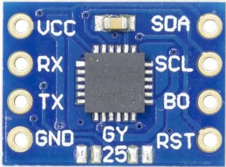
The MPU6050, manufactured by ST with the part ID GY-25, is a 6-axis motion tracking device that integrates a 3-axis gyroscope and a 3-axis accelerometer on a single chip. This compact and versatile sensor is widely used in applications requiring motion sensing and orientation detection. Its ability to measure angular velocity and linear acceleration makes it ideal for robotics, drones, smartphones, gaming devices, and wearable technology.
Explore Projects Built with MPU6050
 Open Project in Cirkit Designer
 Open Project in Cirkit Designer
 Open Project in Cirkit Designer
 Open Project in Cirkit Designer
Explore Projects Built with MPU6050
Open Project in Cirkit DesignerOpen Project in Cirkit DesignerOpen Project in Cirkit DesignerOpen Project in Cirkit DesignerCommon Applications
- Robotics for motion control and stabilization
- Drones for flight stabilization and navigation
- Smartphones for screen orientation and gesture recognition
- Gaming devices for motion-based controls
- Wearable devices for activity tracking and fitness monitoring
Technical Specifications
The MPU6050 offers a range of features and specifications that make it a popular choice for motion sensing applications. Below are the key technical details:
Key Specifications
| Parameter | Value |
|---|---|
| Supply Voltage | 2.375V to 3.46V |
| Operating Current | 3.6 mA (typical) |
| Gyroscope Range | ±250, ±500, ±1000, ±2000 °/s |
| Accelerometer Range | ±2g, ±4g, ±8g, ±16g |
| Communication Interface | I2C (up to 400 kHz) or SPI (up to 1 MHz) |
| Operating Temperature | -40°C to +85°C |
| Package Type | QFN-24 |
Pin Configuration
The MPU6050 has 8 primary pins for interfacing. Below is the pinout description:
| Pin Number | Pin Name | Description |
|---|---|---|
| 1 | VCC | Power supply input (2.375V to 3.46V) |
| 2 | GND | Ground connection |
| 3 | SCL | I2C clock line |
| 4 | SDA | I2C data line |
| 5 | AD0 | I2C address select (connect to GND or VCC) |
| 6 | INT | Interrupt output |
| 7 | FSYNC | Frame synchronization input |
| 8 | CLKIN | Optional external clock input |
Usage Instructions
The MPU6050 is straightforward to use in a circuit, especially with microcontrollers like the Arduino UNO. Below are the steps and best practices for integrating the sensor:
Connecting the MPU6050 to an Arduino UNO
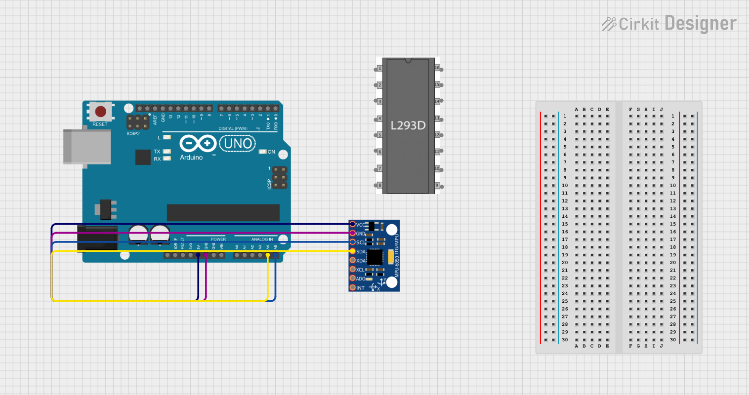
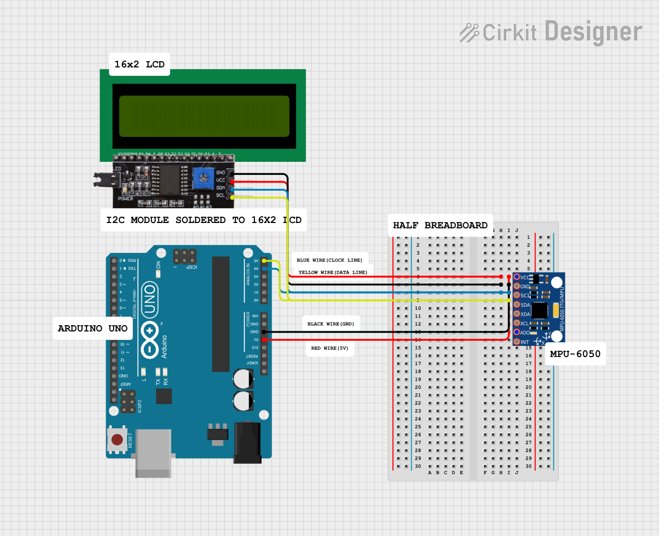
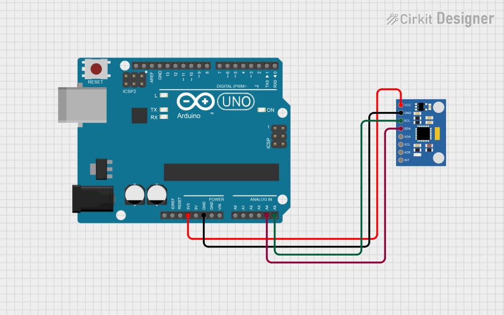
- Power Supply: Connect the VCC pin of the MPU6050 to the 3.3V or 5V pin of the Arduino UNO (the module has an onboard voltage regulator). Connect the GND pin to the Arduino's GND.
- I2C Communication: Connect the SCL pin of the MPU6050 to the A5 pin of the Arduino UNO and the SDA pin to the A4 pin.
- Address Selection: Leave the AD0 pin unconnected or connect it to GND for the default I2C address (0x68). Connect it to VCC to use the alternate address (0x69).
- Interrupt Pin: Optionally, connect the INT pin to a digital pin on the Arduino for interrupt-based applications.
Sample Arduino Code
Below is an example of how to read data from the MPU6050 using the Arduino IDE and the Wire library:
#include <Wire.h>

const int MPU_ADDR = 0x68; // I2C address of the MPU6050 (default is 0x68)

void setup() {
  Wire.begin(); // Initialize I2C communication
  Serial.begin(9600); // Start serial communication for debugging

  // Wake up the MPU6050 (it starts in sleep mode)
  Wire.beginTransmission(MPU_ADDR);
  Wire.write(0x6B); // Access the power management register
  Wire.write(0);    // Set to 0 to wake up the sensor
  Wire.endTransmission();
}

void loop() {
  Wire.beginTransmission(MPU_ADDR);
  Wire.write(0x3B); // Starting register for accelerometer data
  Wire.endTransmission(false);
  Wire.requestFrom(MPU_ADDR, 6, true); // Request 6 bytes of data

  // Read accelerometer data (2 bytes each for X, Y, Z axes)
  int16_t accelX = (Wire.read() << 8) | Wire.read();
  int16_t accelY = (Wire.read() << 8) | Wire.read();
  int16_t accelZ = (Wire.read() << 8) | Wire.read();

  // Print the accelerometer data to the Serial Monitor
  Serial.print("Accel X: "); Serial.print(accelX);
  Serial.print(" | Accel Y: "); Serial.print(accelY);
  Serial.print(" | Accel Z: "); Serial.println(accelZ);

  delay(500); // Delay for readability
}
Best Practices
- Use pull-up resistors (4.7kΩ to 10kΩ) on the SDA and SCL lines if not already included on the breakout board.
- Ensure the I2C address (0x68 or 0x69) matches your configuration.
- Avoid excessive vibrations or shocks to the sensor for accurate readings.
- Use a stable power supply to minimize noise in the measurements.
Troubleshooting and FAQs
Common Issues
No Data or Incorrect Readings:
- Cause: Incorrect wiring or I2C address mismatch.
- Solution: Double-check the connections and ensure the AD0 pin is configured correctly for the desired I2C address.
Sensor Not Detected:
- Cause: Missing pull-up resistors on the I2C lines.
- Solution: Add 4.7kΩ to 10kΩ pull-up resistors to the SDA and SCL lines.
Unstable or Noisy Data:
- Cause: Power supply noise or external vibrations.
- Solution: Use a decoupling capacitor (e.g., 0.1µF) near the VCC pin and minimize vibrations.
Interrupt Pin Not Working:
- Cause: Interrupts not configured in the code.
- Solution: Verify the interrupt configuration in your code and ensure the INT pin is connected to the correct Arduino pin.
FAQs
Q1: Can the MPU6050 be used with a 5V microcontroller?
Yes, the GY-25 breakout board includes a voltage regulator, allowing it to work with 5V microcontrollers like the Arduino UNO.
Q2: What is the maximum sampling rate of the MPU6050?
The MPU6050 supports a maximum sampling rate of 1 kHz.
Q3: Can I use SPI instead of I2C?
The MPU6050 supports SPI communication, but the GY-25 breakout board is typically configured for I2C by default.
Q4: How do I calibrate the MPU6050?
Calibration involves reading the raw sensor data and calculating offsets for the gyroscope and accelerometer. Libraries like MPU6050 or MPU6050_DMP can simplify this process.
By following this documentation, you can effectively integrate and use the MPU6050 in your projects.