How to Use BLDC MOTOR: Examples, Pinouts, and Specs
Introduction
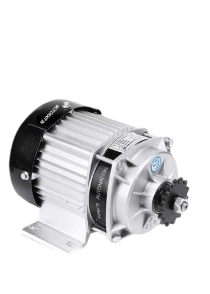
The DAIKIN Brushless DC Motor (BLDC) is an advanced electric motor powered by direct current (DC) electricity. Unlike traditional brushed motors, the BLDC motor uses an electronic controller to switch DC currents to the motor windings, producing magnetic fields that effectively rotate the motor. This design results in higher efficiency, reliability, and longevity. BLDC motors are commonly used in applications such as electric vehicles, drones, HVAC systems, and industrial automation.
Explore Projects Built with BLDC MOTOR
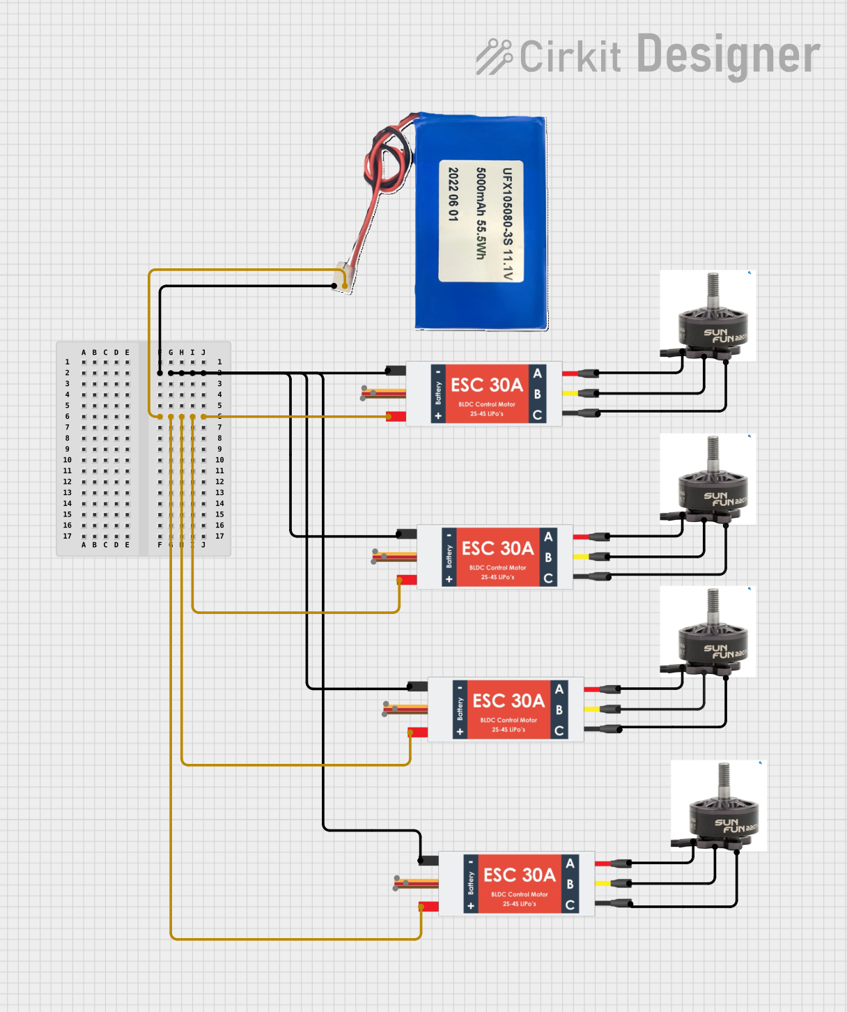

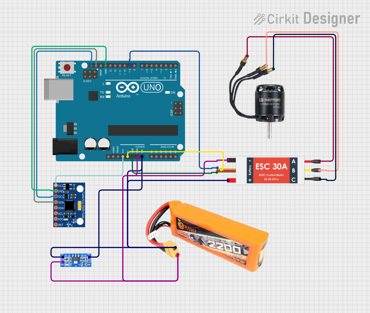
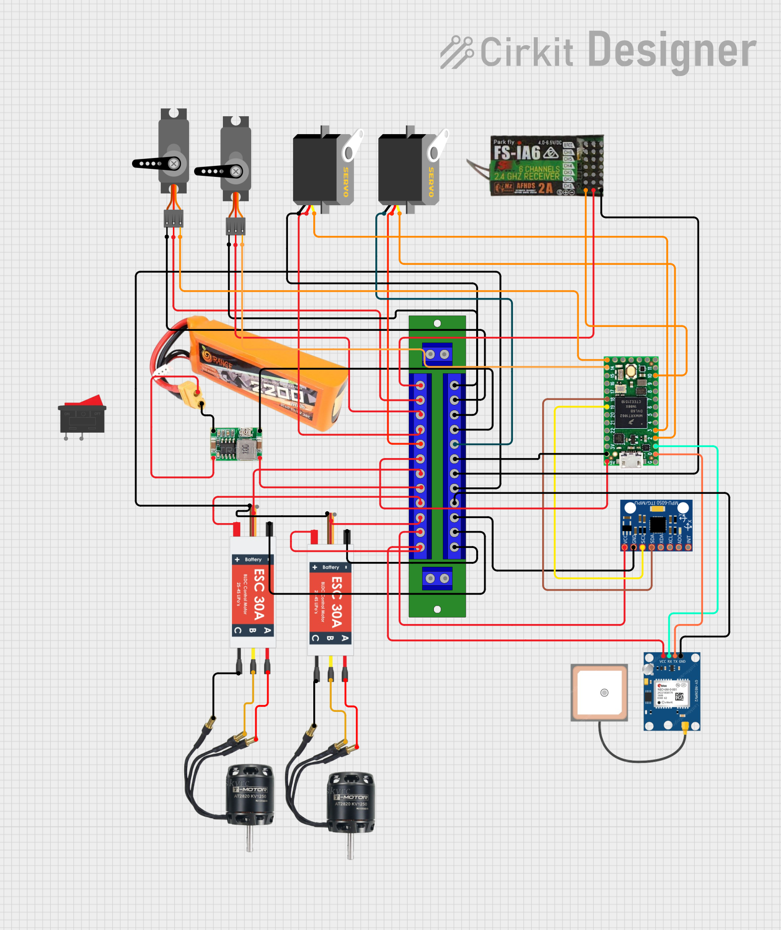
Explore Projects Built with BLDC MOTOR
Technical Specifications
Key Technical Details
| Parameter | Value |
|---|---|
| Manufacturer | DAIKIN |
| Part ID | MOTOR |
| Voltage Rating | 24V DC |
| Current Rating | 5A |
| Power Rating | 120W |
| Speed Range | 0 - 3000 RPM |
| Torque | 0.4 Nm |
| Efficiency | >85% |
| Operating Temperature | -20°C to 60°C |
| Weight | 500g |
Pin Configuration and Descriptions
| Pin Number | Pin Name | Description |
|---|---|---|
| 1 | VCC | Power supply (24V DC) |
| 2 | GND | Ground |
| 3 | HALL_A | Hall sensor A output |
| 4 | HALL_B | Hall sensor B output |
| 5 | HALL_C | Hall sensor C output |
| 6 | PHASE_A | Motor winding phase A |
| 7 | PHASE_B | Motor winding phase B |
| 8 | PHASE_C | Motor winding phase C |
Usage Instructions
How to Use the Component in a Circuit
To use the DAIKIN BLDC motor in a circuit, follow these steps:
- Power Supply: Connect the VCC pin to a 24V DC power supply and the GND pin to the ground.
- Motor Driver: Use a BLDC motor driver/controller to manage the motor's operation. Connect the motor winding phases (PHASE_A, PHASE_B, PHASE_C) to the corresponding outputs on the motor driver.
- Hall Sensors: Connect the Hall sensor outputs (HALL_A, HALL_B, HALL_C) to the motor driver's Hall sensor inputs. These sensors provide feedback for precise control of the motor's position and speed.
- Control Signals: Provide control signals to the motor driver to set the desired speed and direction of the motor.
Important Considerations and Best Practices
- Heat Dissipation: Ensure proper heat dissipation for the motor and driver to prevent overheating.
- Power Supply: Use a stable and sufficient power supply to avoid voltage drops that can affect motor performance.
- Wiring: Use appropriate gauge wires to handle the current requirements and minimize resistance.
- Mounting: Securely mount the motor to prevent vibrations and mechanical stress.
Example: Connecting to an Arduino UNO
To control the DAIKIN BLDC motor using an Arduino UNO, you can use a BLDC motor driver such as the L298N. Below is an example code to control the motor's speed and direction.
// Include necessary libraries
#include <Arduino.h>

// Define motor driver pins
const int ENA = 9;  // Enable pin for motor driver
const int IN1 = 8;  // Input pin 1 for motor driver
const int IN2 = 7;  // Input pin 2 for motor driver

void setup() {
  // Set motor driver pins as outputs
  pinMode(ENA, OUTPUT);
  pinMode(IN1, OUTPUT);
  pinMode(IN2, OUTPUT);
}

void loop() {
  // Set motor direction to forward
  digitalWrite(IN1, HIGH);
  digitalWrite(IN2, LOW);

  // Set motor speed (0-255)
  analogWrite(ENA, 200);

  // Run motor for 5 seconds
  delay(5000);

  // Stop motor
  analogWrite(ENA, 0);

  // Wait for 2 seconds
  delay(2000);

  // Set motor direction to reverse
  digitalWrite(IN1, LOW);
  digitalWrite(IN2, HIGH);

  // Set motor speed (0-255)
  analogWrite(ENA, 200);

  // Run motor for 5 seconds
  delay(5000);

  // Stop motor
  analogWrite(ENA, 0);

  // Wait for 2 seconds
  delay(2000);
}
Troubleshooting and FAQs
Common Issues Users Might Face
Motor Not Spinning:
- Solution: Check the power supply connections and ensure the voltage is correct. Verify that the motor driver is properly connected and receiving control signals.
Overheating:
- Solution: Ensure proper ventilation and heat dissipation. Check for any obstructions or excessive load on the motor.
Erratic Movement:
- Solution: Verify the Hall sensor connections and ensure they are providing accurate feedback. Check for loose or damaged wires.
Low Speed or Torque:
- Solution: Ensure the power supply can provide sufficient current. Check for any mechanical resistance or obstructions.
Solutions and Tips for Troubleshooting
- Check Connections: Ensure all connections are secure and correctly wired.
- Use Proper Power Supply: Verify that the power supply meets the motor's voltage and current requirements.
- Monitor Temperature: Regularly check the motor and driver temperature to prevent overheating.
- Consult Datasheet: Refer to the motor's datasheet for detailed specifications and guidelines.
By following this documentation, users can effectively utilize the DAIKIN BLDC motor in their projects, ensuring optimal performance and reliability.