How to Use Step-Down Converter 12V to 5V, Charging module circuit, QC2.0/QC23.0 Protocol Support: 2-Channels: Examples, Pinouts, and Specs
Introduction
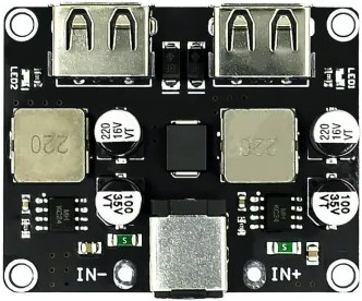
The ENGLAB Buck Converter 12V→5V is a high-efficiency step-down (buck) converter designed to convert a 12V DC input to a stable 5V DC output. This module supports Quick Charge (QC) 2.0 and QC 3.0 protocols, making it ideal for fast-charging applications. With dual-channel output capability, it can simultaneously power multiple devices or circuits. Its compact design and robust performance make it suitable for a wide range of applications, including mobile device charging, embedded systems, and automotive electronics.
Explore Projects Built with Step-Down Converter 12V to 5V, Charging module circuit, QC2.0/QC23.0 Protocol Support: 2-Channels


Explore Projects Built with Step-Down Converter 12V to 5V, Charging module circuit, QC2.0/QC23.0 Protocol Support: 2-Channels
Common Applications
- Fast-charging mobile devices (QC2.0/QC3.0 support)
- Powering 5V microcontrollers (e.g., Arduino, Raspberry Pi)
- Automotive USB power supplies
- Battery-powered systems
- General-purpose DC-DC voltage regulation
Technical Specifications
The following table outlines the key technical specifications of the ENGLAB Buck Converter 12V→5V:
| Parameter | Value |
|---|---|
| Input Voltage Range | 6V to 32V DC |
| Output Voltage | 5V DC (fixed) |
| Output Current | Up to 3A per channel |
| Efficiency | Up to 95% |
| Protocol Support | QC2.0, QC3.0 |
| Channels | 2 (independent outputs) |
| Operating Temperature | -40°C to +85°C |
| Dimensions | 45mm x 25mm x 12mm |
Pin Configuration and Descriptions
The module has the following pinout:
| Pin Name | Type | Description |
|---|---|---|
| VIN+ | Power Input | Positive input voltage (6V to 32V DC). |
| VIN- | Power Input | Ground connection for input voltage. |
| VOUT1+ | Power Output | Positive output voltage for Channel 1 (5V DC). |
| VOUT1- | Power Output | Ground connection for Channel 1. |
| VOUT2+ | Power Output | Positive output voltage for Channel 2 (5V DC). |
| VOUT2- | Power Output | Ground connection for Channel 2. |
| QC_EN | Control Signal | Enables QC2.0/QC3.0 protocol when pulled high. |
Usage Instructions
How to Use the Component in a Circuit
Connect the Input Voltage:
- Connect the positive terminal of your 12V DC power source to the
VIN+pin. - Connect the ground terminal of your power source to the
VIN-pin.
- Connect the positive terminal of your 12V DC power source to the
Connect the Output Load:
- For Channel 1, connect the load's positive terminal to
VOUT1+and the ground terminal toVOUT1-. - For Channel 2, connect the load's positive terminal to
VOUT2+and the ground terminal toVOUT2-.
- For Channel 1, connect the load's positive terminal to
Enable QC Protocol (Optional):
- If you need to use Quick Charge functionality, pull the
QC_ENpin high using a 3.3V or 5V logic signal.
- If you need to use Quick Charge functionality, pull the
Power On:
- Turn on the 12V DC power source. The module will regulate the input voltage to provide a stable 5V output.
Important Considerations and Best Practices
- Input Voltage Range: Ensure the input voltage is within the specified range (6V to 32V). Exceeding this range may damage the module.
- Heat Dissipation: For high-current applications, ensure proper heat dissipation by adding a heatsink or improving airflow around the module.
- Load Current: Do not exceed the maximum output current of 3A per channel to avoid overheating or damage.
- QC Protocol: If using the QC2.0/QC3.0 protocol, ensure the connected device supports these standards.
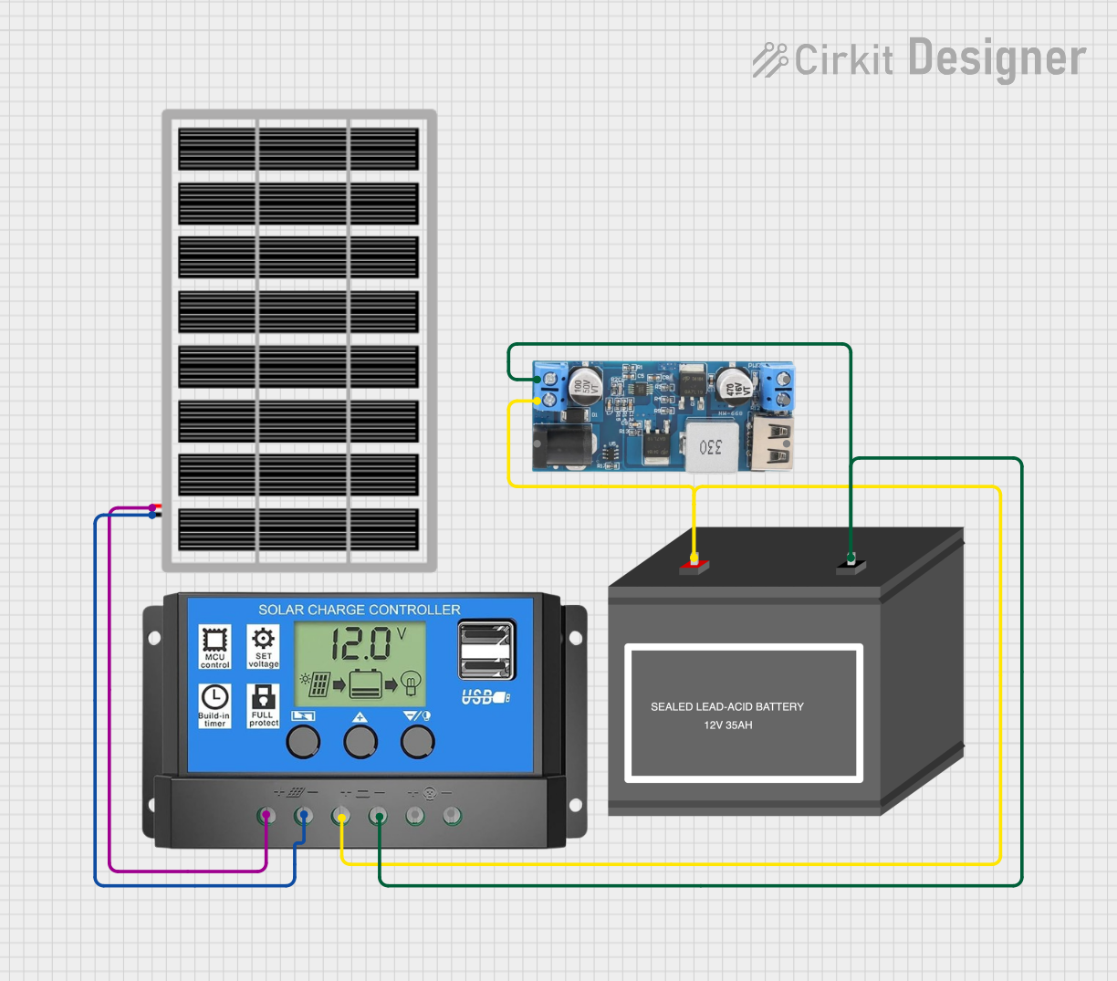
Example: Using with Arduino UNO
The module can be used to power an Arduino UNO from a 12V battery. Here's how to connect it:
- Connect the 12V battery's positive terminal to
VIN+and the negative terminal toVIN-. - Connect
VOUT1+to the Arduino's 5V pin andVOUT1-to the Arduino's GND pin.
Sample Code for QC_EN Pin Control
If you want to control the QC_EN pin using the Arduino, you can use the following code:
// Define the QC_EN pin
const int QC_EN_PIN = 7;

void setup() {
  // Set QC_EN_PIN as an output
  pinMode(QC_EN_PIN, OUTPUT);

  // Enable QC protocol by setting the pin HIGH
  digitalWrite(QC_EN_PIN, HIGH);

  // Optional: Add a delay to ensure stable operation
  delay(100);
}

void loop() {
  // The QC_EN pin remains HIGH to enable QC protocol
  // Add your main code here
}
Troubleshooting and FAQs
Common Issues and Solutions
No Output Voltage:
- Cause: Input voltage is not connected or is outside the specified range.
- Solution: Verify the input voltage is between 6V and 32V and properly connected.
Overheating:
- Cause: Excessive load current or poor heat dissipation.
- Solution: Reduce the load current or add a heatsink to the module.
QC Protocol Not Working:
- Cause:
QC_ENpin is not enabled or the connected device does not support QC2.0/QC3.0. - Solution: Pull the
QC_ENpin high and ensure the connected device supports QC protocols.
- Cause:
Voltage Drop Under Load:
- Cause: Input power source cannot supply sufficient current.
- Solution: Use a power source with a higher current rating.
FAQs
Q1: Can I use this module with a 24V input?
A1: Yes, the module supports input voltages up to 32V. Ensure the input voltage is stable and within the specified range.
Q2: Can I connect both channels to the same load?
A2: No, each channel is designed to operate independently. Connecting them together may cause instability or damage.
Q3: Is the module protected against reverse polarity?
A3: No, the module does not have built-in reverse polarity protection. Always double-check your connections before powering on.
Q4: Can I use this module to charge a Li-ion battery?
A4: Yes, but ensure the battery charging circuit is compatible with a 5V input and supports QC protocols if needed.