Cirkit Designer Logo
Cirkit Designer
Your all-in-one circuit design IDE
Home / 
Component Documentation

How to Use Hotbed MOSFET: Examples, Pinouts, and Specs

Image of Hotbed MOSFET
Cirkit Designer LogoDesign with Hotbed MOSFET in Cirkit Designer

Introduction

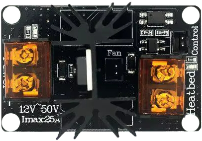
A Hotbed MOSFET is a specialized transistor designed to control high-current loads, such as the heating elements used in 3D printers. It functions as an electronic switch, allowing or blocking current flow based on an input signal. This component is engineered to handle the significant thermal and electrical demands of heating applications, ensuring reliable and efficient operation.

Explore Projects Built with Hotbed MOSFET

Use Cirkit Designer to design, explore, and prototype these projects online. Some projects support real-time simulation. Click "Open Project" to start designing instantly!
Battery-Powered Fan Controller with NTC Thermistor and IRFZ44N MOSFET
Image of Temperature Controlled Fan: A project utilizing Hotbed MOSFET in a practical application
This circuit is a temperature-controlled fan system. It uses an NTC thermistor to sense temperature changes, which then modulates the gate of an IRFZ44N MOSFET through a resistor. The MOSFET controls the power to a fan, turning it on or off based on the temperature, with power supplied by a 12V battery.
Cirkit Designer LogoOpen Project in Cirkit Designer
ESP8266 NodeMCU Based Temperature-Controlled Fan System
Image of Temp based Fan speed control: A project utilizing Hotbed MOSFET in a practical application
This circuit features an ESP8266 NodeMCU microcontroller interfaced with a DS18B20 temperature sensor and a 12V fan controlled by a MOSFET. The 7805 voltage regulator, along with electrolytic capacitors for stabilization, steps down the 12V supply to 5V to power the NodeMCU. The temperature readings from the DS18B20 can be used by the NodeMCU to control the fan speed via the MOSFET, likely for thermal management purposes.
Cirkit Designer LogoOpen Project in Cirkit Designer
ESP32-Controlled Mosfet Switch for Nichrome Wire Heating
Image of AUTOMATC ribbon cutter: A project utilizing Hotbed MOSFET in a practical application
This circuit appears to be a simple control circuit for a nichrome wire heating element, powered by a 12V battery. The ESP32 microcontroller is used to switch the Mosfet on and off, allowing current to flow through the nichrome wire. A resistor is connected to the gate of the Mosfet to limit the current from the ESP32's GPIO pin.
Cirkit Designer LogoOpen Project in Cirkit Designer
ESP8266 NodeMCU Based Temperature Monitoring System with LCD Display and Fan Control
Image of Temp: A project utilizing Hotbed MOSFET in a practical application
This circuit features an ESP8266 NodeMCU microcontroller interfaced with a DS18B20 temperature sensor, an I2C LCD display, and an IRFZ44N MOSFET controlling a 12V fan. The temperature sensor is connected to the microcontroller through a pull-up resistor, and the microcontroller regulates the fan speed based on the temperature readings. A 7805 voltage regulator with accompanying electrolytic capacitors provides a stable 5V supply to the microcontroller and the LCD, while the 12V power supply directly powers the fan through the MOSFET.
Cirkit Designer LogoOpen Project in Cirkit Designer

Explore Projects Built with Hotbed MOSFET

Use Cirkit Designer to design, explore, and prototype these projects online. Some projects support real-time simulation. Click "Open Project" to start designing instantly!
Image of Temperature Controlled Fan: A project utilizing Hotbed MOSFET in a practical application
Battery-Powered Fan Controller with NTC Thermistor and IRFZ44N MOSFET
This circuit is a temperature-controlled fan system. It uses an NTC thermistor to sense temperature changes, which then modulates the gate of an IRFZ44N MOSFET through a resistor. The MOSFET controls the power to a fan, turning it on or off based on the temperature, with power supplied by a 12V battery.
Cirkit Designer LogoOpen Project in Cirkit Designer
Image of Temp based Fan speed control: A project utilizing Hotbed MOSFET in a practical application
ESP8266 NodeMCU Based Temperature-Controlled Fan System
This circuit features an ESP8266 NodeMCU microcontroller interfaced with a DS18B20 temperature sensor and a 12V fan controlled by a MOSFET. The 7805 voltage regulator, along with electrolytic capacitors for stabilization, steps down the 12V supply to 5V to power the NodeMCU. The temperature readings from the DS18B20 can be used by the NodeMCU to control the fan speed via the MOSFET, likely for thermal management purposes.
Cirkit Designer LogoOpen Project in Cirkit Designer
Image of AUTOMATC ribbon cutter: A project utilizing Hotbed MOSFET in a practical application
ESP32-Controlled Mosfet Switch for Nichrome Wire Heating
This circuit appears to be a simple control circuit for a nichrome wire heating element, powered by a 12V battery. The ESP32 microcontroller is used to switch the Mosfet on and off, allowing current to flow through the nichrome wire. A resistor is connected to the gate of the Mosfet to limit the current from the ESP32's GPIO pin.
Cirkit Designer LogoOpen Project in Cirkit Designer
Image of Temp: A project utilizing Hotbed MOSFET in a practical application
ESP8266 NodeMCU Based Temperature Monitoring System with LCD Display and Fan Control
This circuit features an ESP8266 NodeMCU microcontroller interfaced with a DS18B20 temperature sensor, an I2C LCD display, and an IRFZ44N MOSFET controlling a 12V fan. The temperature sensor is connected to the microcontroller through a pull-up resistor, and the microcontroller regulates the fan speed based on the temperature readings. A 7805 voltage regulator with accompanying electrolytic capacitors provides a stable 5V supply to the microcontroller and the LCD, while the 12V power supply directly powers the fan through the MOSFET.
Cirkit Designer LogoOpen Project in Cirkit Designer

Common Applications and Use Cases

  • Controlling the heated bed in 3D printers
  • Driving high-power resistive loads, such as heating elements
  • Power management in high-current circuits
  • Applications requiring efficient thermal dissipation and high switching speeds

Technical Specifications

Key Technical Details

  • Operating Voltage (VDS): Typically up to 24V (varies by model)
  • Maximum Current (ID): 25A to 50A (depending on the specific MOSFET model)
  • Gate Threshold Voltage (VGS(th)): 2V to 4V
  • On-Resistance (RDS(on)): As low as 0.001Ω for efficient power handling
  • Power Dissipation: Up to 150W (with proper heat sinking)
  • Control Signal Voltage: 3.3V or 5V logic compatible
  • Thermal Management: Integrated heat sink or external heat sink required for high loads

Pin Configuration and Descriptions

The Hotbed MOSFET module typically has the following pin configuration:

Pin Name Description
VIN+ Positive input voltage for the heating element (e.g., 12V or 24V).
VIN- Ground connection for the input voltage.
BED+ Positive output terminal connected to the heating element.
BED- Ground connection for the heating element.
Signal Control signal input from the microcontroller (e.g., Arduino, 3D printer board).
GND Ground connection for the control signal.

Usage Instructions

How to Use the Component in a Circuit

  1. Power Connections:

    • Connect the VIN+ and VIN- terminals to the power supply (e.g., 12V or 24V).
    • Ensure the power supply can handle the current requirements of the heating element.
  2. Load Connections:

    • Connect the heating element (e.g., 3D printer hotbed) to the BED+ and BED- terminals.
    • Ensure proper polarity and secure connections to avoid loose contacts.
  3. Control Signal:

    • Connect the Signal pin to the control output of your microcontroller or 3D printer mainboard.
    • Connect the GND pin to the ground of the control circuit.
  4. Thermal Management:

    • Attach a heat sink to the MOSFET if it is not already integrated.
    • Use thermal paste for better heat dissipation if required.
    • Ensure adequate airflow around the MOSFET to prevent overheating.
  5. Testing:

    • Power on the circuit and send a control signal to the MOSFET.
    • Verify that the heating element operates as expected.

Important Considerations and Best Practices

  • Voltage Compatibility: Ensure the input voltage matches the specifications of the MOSFET and the heating element.
  • Current Rating: Verify that the MOSFET can handle the maximum current required by the load.
  • Heat Dissipation: Always use a heat sink or active cooling for high-current applications.
  • Signal Voltage: Confirm that the control signal voltage is within the MOSFET's gate threshold range.
  • Wiring: Use thick wires for high-current connections to minimize resistance and heat generation.

Example Code for Arduino UNO

Below is an example of how to control a Hotbed MOSFET using an Arduino UNO:

// Define the pin connected to the MOSFET signal input
const int mosfetPin = 9;

void setup() {
  // Set the MOSFET pin as an output
  pinMode(mosfetPin, OUTPUT);
}

void loop() {
  // Turn on the heating element by setting the MOSFET pin HIGH
  digitalWrite(mosfetPin, HIGH);
  delay(5000); // Keep the heating element on for 5 seconds

  // Turn off the heating element by setting the MOSFET pin LOW
  digitalWrite(mosfetPin, LOW);
  delay(5000); // Keep the heating element off for 5 seconds
}

Note: Replace the delay() function with a more sophisticated control mechanism (e.g., PID control) for real-world applications like 3D printing.

Troubleshooting and FAQs

Common Issues and Solutions

  1. Heating Element Does Not Turn On:

    • Cause: Incorrect wiring or insufficient control signal voltage.
    • Solution: Double-check all connections and ensure the control signal voltage matches the MOSFET's gate threshold.
  2. MOSFET Overheats:

    • Cause: Insufficient heat dissipation or excessive current.
    • Solution: Attach a heat sink or improve airflow around the MOSFET. Verify that the load current is within the MOSFET's rated capacity.
  3. Heating Element Stays On Permanently:

    • Cause: Gate signal stuck at HIGH or damaged MOSFET.
    • Solution: Check the control signal and replace the MOSFET if necessary.
  4. Control Signal Not Detected:

    • Cause: Faulty microcontroller output or loose connections.
    • Solution: Test the microcontroller output with a multimeter and secure all connections.

FAQs

  • Q: Can I use a Hotbed MOSFET with a 5V heating element?
    A: No, most Hotbed MOSFETs are designed for 12V or 24V systems. Check the specifications of your MOSFET and heating element.

  • Q: Do I need a separate power supply for the MOSFET?
    A: The MOSFET typically shares the same power supply as the heating element. Ensure the power supply can handle the combined load.

  • Q: How do I know if the MOSFET is damaged?
    A: If the MOSFET overheats excessively, fails to switch, or causes the heating element to stay on permanently, it may be damaged and require replacement.