How to Use Nano 3.0 ATmega328P Type-C USB CH340 Controller Board: Examples, Pinouts, and Specs
Introduction
The Nano 3.0 ATmega328P Type-C USB CH340 Controller Board by HiLetgo is a compact and versatile microcontroller board designed for a wide range of DIY electronics projects and prototyping applications. It is based on the ATmega328P microcontroller and features a Type-C USB interface for easy connectivity and programming. This board is an excellent choice for hobbyists and professionals alike, offering the functionality of an Arduino Nano with the added convenience of a modern USB Type-C connector.
Explore Projects Built with Nano 3.0 ATmega328P Type-C USB CH340 Controller Board


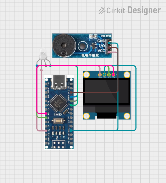
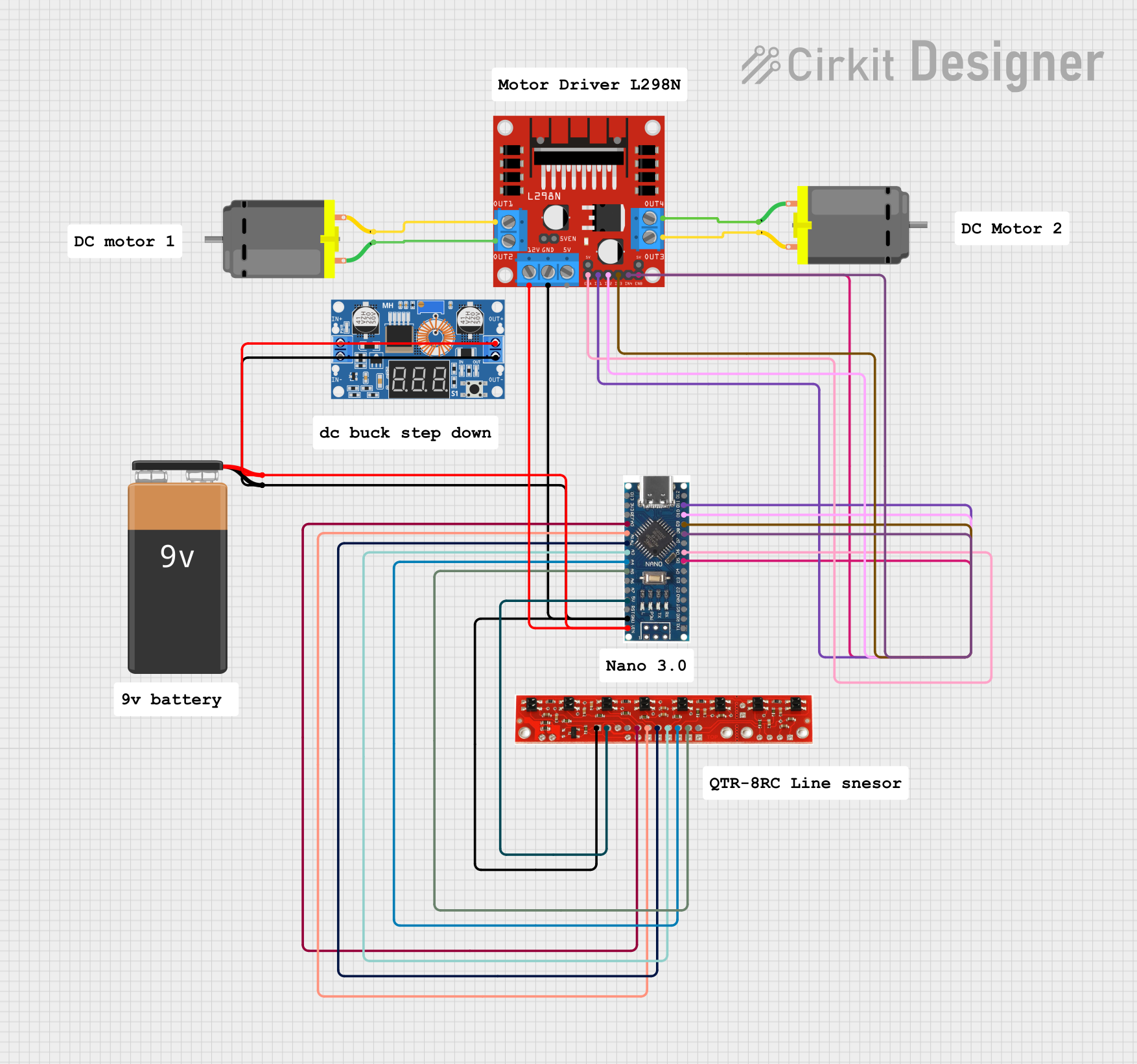
Explore Projects Built with Nano 3.0 ATmega328P Type-C USB CH340 Controller Board
Common Applications and Use Cases
- DIY electronics projects
- Prototyping and testing circuits
- Robotics and automation systems
- IoT (Internet of Things) devices
- Sensor interfacing and data logging
- Educational purposes for learning microcontroller programming
Technical Specifications
Below are the key technical details of the Nano 3.0 ATmega328P Type-C USB CH340 Controller Board:
| Specification | Details |
|---|---|
| Microcontroller | ATmega328P |
| USB Interface | Type-C USB |
| USB-to-Serial Chip | CH340 |
| Operating Voltage | 5V |
| Input Voltage (VIN pin) | 7-12V |
| Digital I/O Pins | 14 (6 of which provide PWM output) |
| Analog Input Pins | 8 |
| Flash Memory | 32 KB (2 KB used by bootloader) |
| SRAM | 2 KB |
| EEPROM | 1 KB |
| Clock Speed | 16 MHz |
| Dimensions | 43 mm x 18 mm |
| Weight | ~7 g |
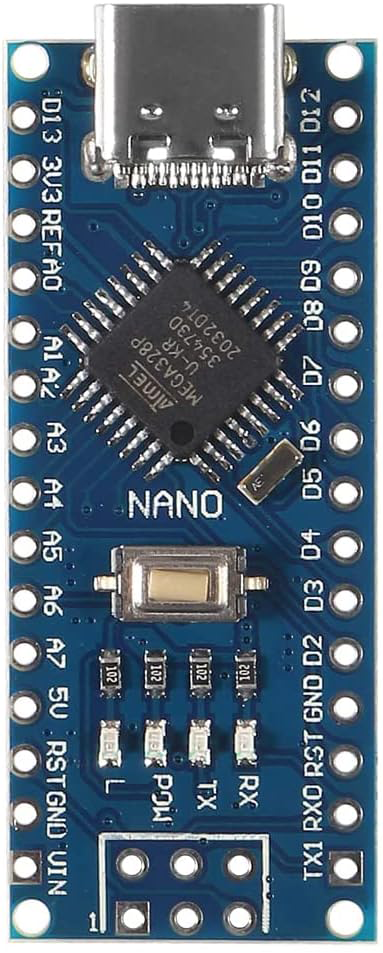
Pin Configuration and Descriptions
The Nano 3.0 board has a total of 30 pins, including digital, analog, power, and communication pins. Below is the pin configuration:
Digital Pins
| Pin Number | Function | Description |
|---|---|---|
| D0 (RX) | UART Receive | Used for serial communication (receives data). |
| D1 (TX) | UART Transmit | Used for serial communication (transmits data). |
| D2-D13 | Digital I/O | General-purpose digital input/output pins. |
| D3, D5, D6, D9, D10, D11 | PWM Output | Pulse Width Modulation output for controlling motors, LEDs, etc. |
Analog Pins
| Pin Number | Function | Description |
|---|---|---|
| A0-A7 | Analog Input | Used to read analog signals (0-5V) from sensors or other devices. |
Power Pins
| Pin Name | Function | Description |
|---|---|---|
| VIN | Input Voltage | External power input (7-12V). |
| 5V | Regulated 5V Output | Provides 5V power to external components. |
| 3.3V | Regulated 3.3V Output | Provides 3.3V power to external components. |
| GND | Ground | Common ground for the circuit. |
Communication Pins
| Pin Name | Function | Description |
|---|---|---|
| SDA | I2C Data | Data line for I2C communication. |
| SCL | I2C Clock | Clock line for I2C communication. |
| MOSI | SPI Master Out, Slave In | SPI data line for communication with SPI devices. |
| MISO | SPI Master In, Slave Out | SPI data line for communication with SPI devices. |
| SCK | SPI Clock | Clock line for SPI communication. |
Usage Instructions
How to Use the Nano 3.0 in a Circuit
Powering the Board:
- Connect the board to your computer using a Type-C USB cable for power and programming.
- Alternatively, supply power through the VIN pin (7-12V) or the 5V pin (regulated 5V).
Programming the Board:
- Install the Arduino IDE on your computer.
- Install the CH340 driver if your computer does not recognize the board.
- Select "Arduino Nano" as the board type and "ATmega328P (Old Bootloader)" as the processor in the Arduino IDE.
- Write your code and upload it to the board via the Type-C USB connection.
Connecting Components:
- Use the digital and analog pins to connect sensors, actuators, and other components.
- Ensure proper grounding and voltage levels to avoid damage to the board or connected devices.
Important Considerations and Best Practices
- Voltage Levels: Ensure that the input voltage does not exceed the specified range (7-12V for VIN, 5V for 5V pin).
- Pin Current Limits: Each I/O pin can source or sink a maximum of 40 mA. Exceeding this limit may damage the microcontroller.
- CH340 Driver: Install the CH340 driver on your computer to enable USB communication. The driver is available for Windows, macOS, and Linux.
- Static Protection: Handle the board with care to avoid static discharge, which can damage the microcontroller.
Example Code for Arduino UNO-Compatible Projects
The following example demonstrates how to blink an LED connected to pin D13:
// This example code blinks an LED connected to pin D13 on the Nano 3.0 board.
// The LED will turn on for 1 second and off for 1 second in a loop.

void setup() {
  pinMode(13, OUTPUT); // Set pin D13 as an output pin
}

void loop() {
  digitalWrite(13, HIGH); // Turn the LED on
  delay(1000);            // Wait for 1 second
  digitalWrite(13, LOW);  // Turn the LED off
  delay(1000);            // Wait for 1 second
}
Troubleshooting and FAQs
Common Issues and Solutions
Board Not Recognized by Computer:
- Ensure the CH340 driver is installed correctly.
- Try using a different Type-C USB cable (some cables are power-only and do not support data transfer).
Upload Error in Arduino IDE:
- Verify that the correct board type ("Arduino Nano") and processor ("ATmega328P (Old Bootloader)") are selected.
- Check the COM port in the Arduino IDE and ensure it matches the one assigned to the board.
No Power to the Board:
- Check the USB connection or external power supply.
- Ensure the power source provides sufficient voltage and current.
Components Not Working as Expected:
- Double-check wiring and connections.
- Verify that the code uploaded to the board is correct and matches the circuit design.
FAQs
Q: Can I power the board using a battery?
A: Yes, you can power the board using a 7-12V battery connected to the VIN pin or a 5V regulated power source connected to the 5V pin.
Q: Is the Nano 3.0 compatible with Arduino shields?
A: The Nano 3.0 is not directly compatible with standard Arduino shields due to its smaller size, but you can use jumper wires to connect shields to the board.
Q: How do I reset the board?
A: Press the reset button on the board to restart the microcontroller. This can be useful for troubleshooting or re-uploading code.