
How to Use INTER MANUEL_230_2P: Examples, Pinouts, and Specs
 Design with INTER MANUEL_230_2P in Cirkit Designer
Introduction
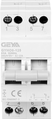
The INTER MANUEL_230_2P, manufactured by GEYA, is a manual switch designed for controlling electrical circuits operating at 230V. This two-pole switch is ideal for applications requiring the simultaneous control of multiple circuits or devices. Its robust design ensures reliable operation in residential, commercial, and industrial environments.
Explore Projects Built with INTER MANUEL_230_2P
 Open Project in Cirkit Designer
 Open Project in Cirkit Designer
 Open Project in Cirkit Designer
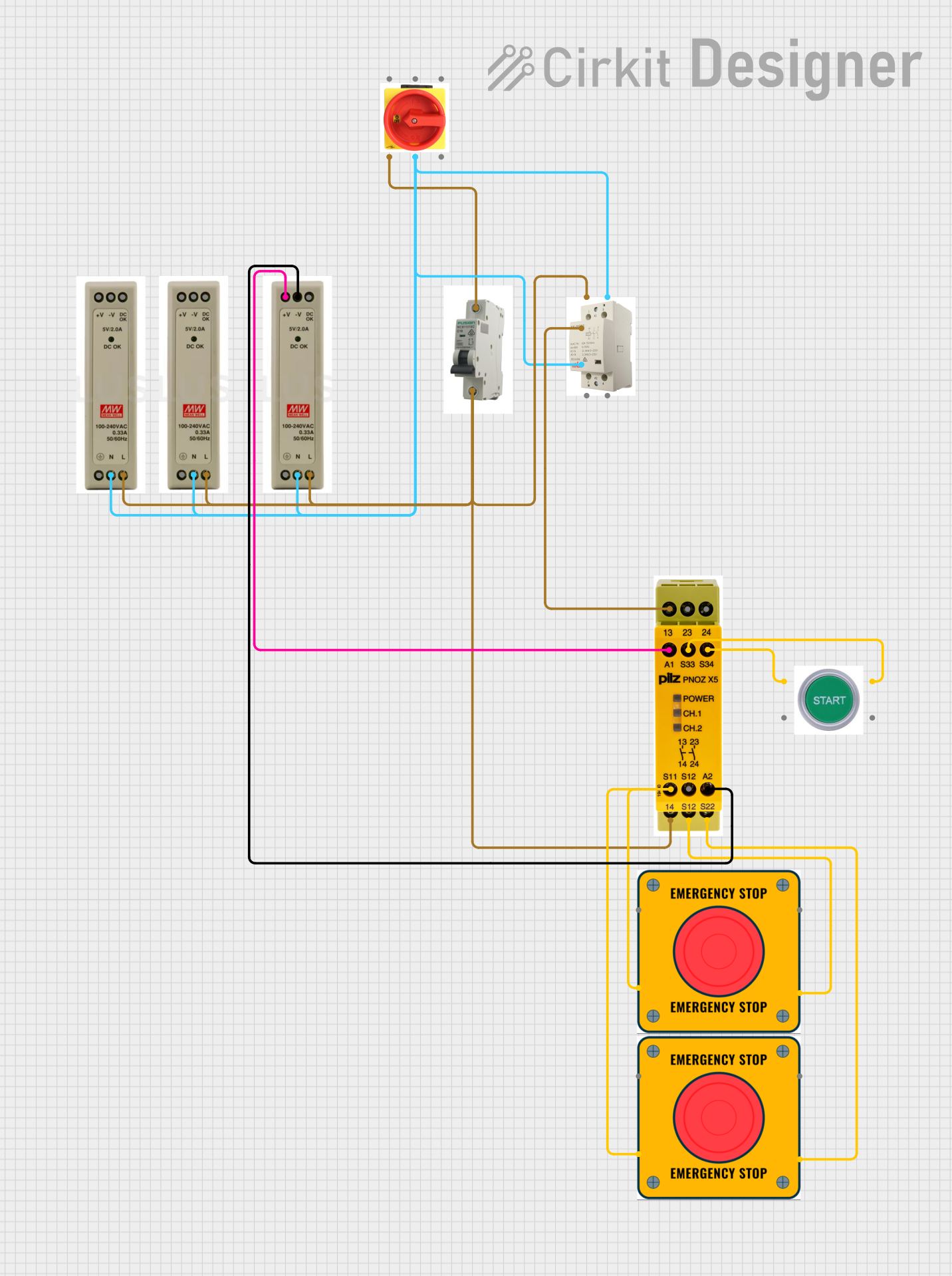 Open Project in Cirkit Designer
Explore Projects Built with INTER MANUEL_230_2P
Open Project in Cirkit DesignerOpen Project in Cirkit DesignerOpen Project in Cirkit DesignerOpen Project in Cirkit DesignerCommon Applications and Use Cases
- Residential Power Control: Used in homes to manually control lighting or appliances.
- Industrial Equipment: Suitable for switching machinery or equipment in industrial setups.
- Backup Power Systems: Often used in manual transfer switches for backup generators.
- Commercial Buildings: Controls multiple circuits in offices or retail spaces.
Technical Specifications
The following table outlines the key technical details of the INTER MANUEL_230_2P:
| Parameter | Specification |
|---|---|
| Rated Voltage | 230V AC |
| Rated Current | 32A |
| Number of Poles | 2 |
| Switching Mechanism | Manual |
| Operating Temperature | -20°C to 55°C |
| Mounting Type | DIN Rail |
| Dimensions | 90mm x 36mm x 60mm |
| Compliance Standards | IEC 60947-3 |
Pin Configuration and Descriptions
The INTER MANUEL_230_2P features a straightforward terminal configuration for easy installation. The table below describes the terminal connections:
| Terminal | Description |
|---|---|
| L1 | Input for the first pole (live wire) |
| L2 | Input for the second pole (live wire) |
| T1 | Output for the first pole (connected load) |
| T2 | Output for the second pole (connected load) |
| Ground | Optional grounding terminal for safety (if present) |
Usage Instructions
How to Use the Component in a Circuit
- Mounting: Secure the INTER MANUEL_230_2P onto a DIN rail in your electrical panel.
- Wiring:
- Connect the live input wires to terminals L1 and L2.
- Connect the output wires leading to the load to terminals T1 and T2.
- If a grounding terminal is present, connect it to the system ground for safety.
- Operation:
- Use the manual lever to switch the circuit ON or OFF.
- Ensure the switch is in the OFF position before performing any maintenance.
Important Considerations and Best Practices
- Voltage and Current Ratings: Do not exceed the rated voltage (230V) or current (32A) to avoid damage or hazards.
- Proper Grounding: Always ground the switch if a grounding terminal is available.
- Secure Connections: Ensure all wires are tightly secured to prevent loose connections.
- Environmental Conditions: Avoid installing the switch in areas with excessive moisture or temperatures outside the -20°C to 55°C range.
Arduino UNO Integration
While the INTER MANUEL_230_2P is not directly compatible with Arduino due to its manual operation and high voltage rating, it can be used in conjunction with relays or contactors controlled by an Arduino. Below is an example of how to use an Arduino to control a relay that operates the INTER MANUEL_230_2P:
// Example code to control a relay with Arduino
const int relayPin = 7; // Pin connected to the relay module

void setup() {
  pinMode(relayPin, OUTPUT); // Set relay pin as output
  digitalWrite(relayPin, LOW); // Ensure relay is off at startup
}

void loop() {
  digitalWrite(relayPin, HIGH); // Turn relay ON
  delay(5000); // Keep relay ON for 5 seconds
  digitalWrite(relayPin, LOW); // Turn relay OFF
  delay(5000); // Keep relay OFF for 5 seconds
}
Note: Ensure proper isolation between the Arduino and the high-voltage circuit controlled by the INTER MANUEL_230_2P.
Troubleshooting and FAQs
Common Issues Users Might Face
Switch Does Not Operate:
- Cause: Loose or incorrect wiring.
- Solution: Double-check all connections and ensure wires are securely fastened.
Overheating:
- Cause: Exceeding the rated current (32A).
- Solution: Verify the load current and ensure it is within the specified limit.
Sparking During Operation:
- Cause: Faulty or worn-out contacts.
- Solution: Inspect the switch contacts and replace the unit if necessary.
Switch Fails to Stay in Position:
- Cause: Mechanical wear or damage.
- Solution: Replace the switch if the lever mechanism is damaged.
Solutions and Tips for Troubleshooting
- Always turn off the power supply before inspecting or troubleshooting the switch.
- Use a multimeter to verify continuity and ensure proper operation of the switch.
- If the switch is part of a larger system, isolate it to determine if the issue lies with the switch or another component.
By following this documentation, users can effectively install, operate, and troubleshoot the INTER MANUEL_230_2P for a wide range of applications.