How to Use TMC5160: Examples, Pinouts, and Specs
Introduction
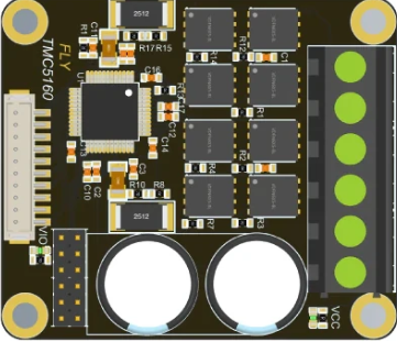
The TMC5160 is a high-performance stepper motor driver designed for precise control of stepper motors. It features advanced microstepping capabilities, integrated current sensing, and a range of programmable settings to optimize motor performance and efficiency. This component is ideal for applications requiring smooth motion, high torque, and low noise.
Explore Projects Built with TMC5160


Explore Projects Built with TMC5160
Common Applications
- 3D printers
- CNC machines
- Robotics
- Industrial automation
- Precision positioning systems
Technical Specifications
Key Technical Details
| Parameter | Value |
|---|---|
| Supply Voltage (VM) | 8V to 60V |
| Logic Voltage (VIO) | 3.3V to 5V |
| Maximum Motor Current | Up to 20A (with external MOSFETs) |
| Microstepping Resolution | Up to 256 microsteps per full step |
| Communication Interface | SPI |
| Integrated Features | Current sensing, stall detection, and more |
| Operating Temperature Range | -40°C to +125°C |
Pin Configuration and Descriptions
The TMC5160 is typically available in a 48-pin QFN package. Below is a summary of the key pins:
| Pin Name | Type | Description |
|---|---|---|
| VM | Power | Motor power supply (8V to 60V) |
| VIO | Power | Logic voltage supply (3.3V or 5V) |
| GND | Ground | Ground connection |
| SPI_MOSI | Input | SPI data input (Master Out Slave In) |
| SPI_MISO | Output | SPI data output (Master In Slave Out) |
| SPI_SCK | Input | SPI clock signal |
| SPI_CS | Input | SPI chip select |
| ENN | Input | Enable pin (active low) |
| STEP | Input | Step pulse input for stepper motor control |
| DIR | Input | Direction control input |
| DIAG0/DIAG1 | Output | Diagnostic outputs for error/status signals |
| AIN | Input | Analog input for current scaling |
| OUT1A/OUT1B | Output | Motor coil 1 outputs |
| OUT2A/OUT2B | Output | Motor coil 2 outputs |
For a complete pinout, refer to the manufacturer's datasheet.
Usage Instructions
How to Use the TMC5160 in a Circuit
- Power Supply: Connect the motor power supply (VM) and logic voltage supply (VIO) to the appropriate pins. Ensure the voltage levels are within the specified range.
- SPI Communication: Connect the SPI interface (MOSI, MISO, SCK, CS) to a microcontroller or processor for configuration and control.
- Motor Connections: Connect the stepper motor coils to the OUT1A/OUT1B and OUT2A/OUT2B pins.
- Control Signals: Use the STEP and DIR pins to control the motor's movement and direction.
- Configuration: Program the TMC5160 using SPI commands to set parameters such as microstepping resolution, current limits, and stall detection thresholds.
Important Considerations
- Heat Dissipation: The TMC5160 can generate significant heat during operation. Use a heatsink or ensure proper PCB thermal design to prevent overheating.
- Current Limiting: Configure the current limit to match the motor's rated current to avoid damage.
- Decoupling Capacitors: Place decoupling capacitors close to the VM and VIO pins to stabilize the power supply.
- Stall Detection: Enable and configure the stall detection feature for applications requiring precise position control.
Example Code for Arduino UNO
Below is an example of how to interface the TMC5160 with an Arduino UNO using SPI:
#include <SPI.h>

// Define SPI pins for Arduino UNO
#define CS_PIN 10  // Chip Select pin
#define STEP_PIN 9 // Step pin
#define DIR_PIN 8  // Direction pin

void setup() {
  // Initialize SPI communication
  SPI.begin();
  pinMode(CS_PIN, OUTPUT);
  pinMode(STEP_PIN, OUTPUT);
  pinMode(DIR_PIN, OUTPUT);

  digitalWrite(CS_PIN, HIGH); // Set CS pin high (inactive)

  // Example: Configure TMC5160 via SPI
  digitalWrite(CS_PIN, LOW); // Select TMC5160
  SPI.transfer(0x80);        // Write command to register 0x00
  SPI.transfer(0x00);        // Example data (configure as needed)
  digitalWrite(CS_PIN, HIGH); // Deselect TMC5160
}

void loop() {
  // Example: Generate step pulses
  digitalWrite(DIR_PIN, HIGH); // Set direction
  digitalWrite(STEP_PIN, HIGH);
  delayMicroseconds(10);       // Pulse width
  digitalWrite(STEP_PIN, LOW);
  delayMicroseconds(1000);     // Step interval
}
Note: Replace the SPI transfer commands with appropriate register addresses and data based on your application.
Troubleshooting and FAQs
Common Issues and Solutions
Motor Not Moving:
- Verify power supply connections and ensure VM and VIO are within the specified range.
- Check the STEP and DIR signals for proper pulse generation.
- Ensure the motor coils are connected correctly to the output pins.
Overheating:
- Use a heatsink or improve PCB thermal design.
- Reduce the motor current limit via SPI configuration.
SPI Communication Failure:
- Check the SPI wiring and ensure the CS pin is toggled correctly.
- Verify the SPI clock speed is compatible with the TMC5160.
Stall Detection Not Working:
- Ensure stall detection is enabled and configured correctly via SPI.
- Adjust the sensitivity settings based on the motor and load.
FAQs
Q: Can the TMC5160 operate without SPI?
A: Yes, the TMC5160 can operate in standalone mode with pre-configured settings, but SPI is required for advanced configuration.
Q: What is the maximum step rate?
A: The TMC5160 supports step rates up to 250 kHz, depending on the microcontroller and configuration.
Q: How do I calculate the current limit?
A: Use the formula provided in the datasheet: I_RMS = (V_REF / (R_SENSE * 32)). Adjust V_REF via the AIN pin or SPI.
For further details, refer to the TMC5160 datasheet and application notes.