
How to Use Diode: Examples, Pinouts, and Specs
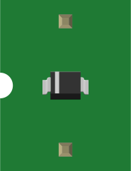
 Design with Diode in Cirkit Designer
Introduction
A diode is a semiconductor device that allows current to flow in one direction only, acting as a one-way valve for electrical current. It is one of the most fundamental components in electronics and is widely used in various applications. Diodes are essential for rectification, signal demodulation, voltage regulation, and circuit protection.
Explore Projects Built with Diode
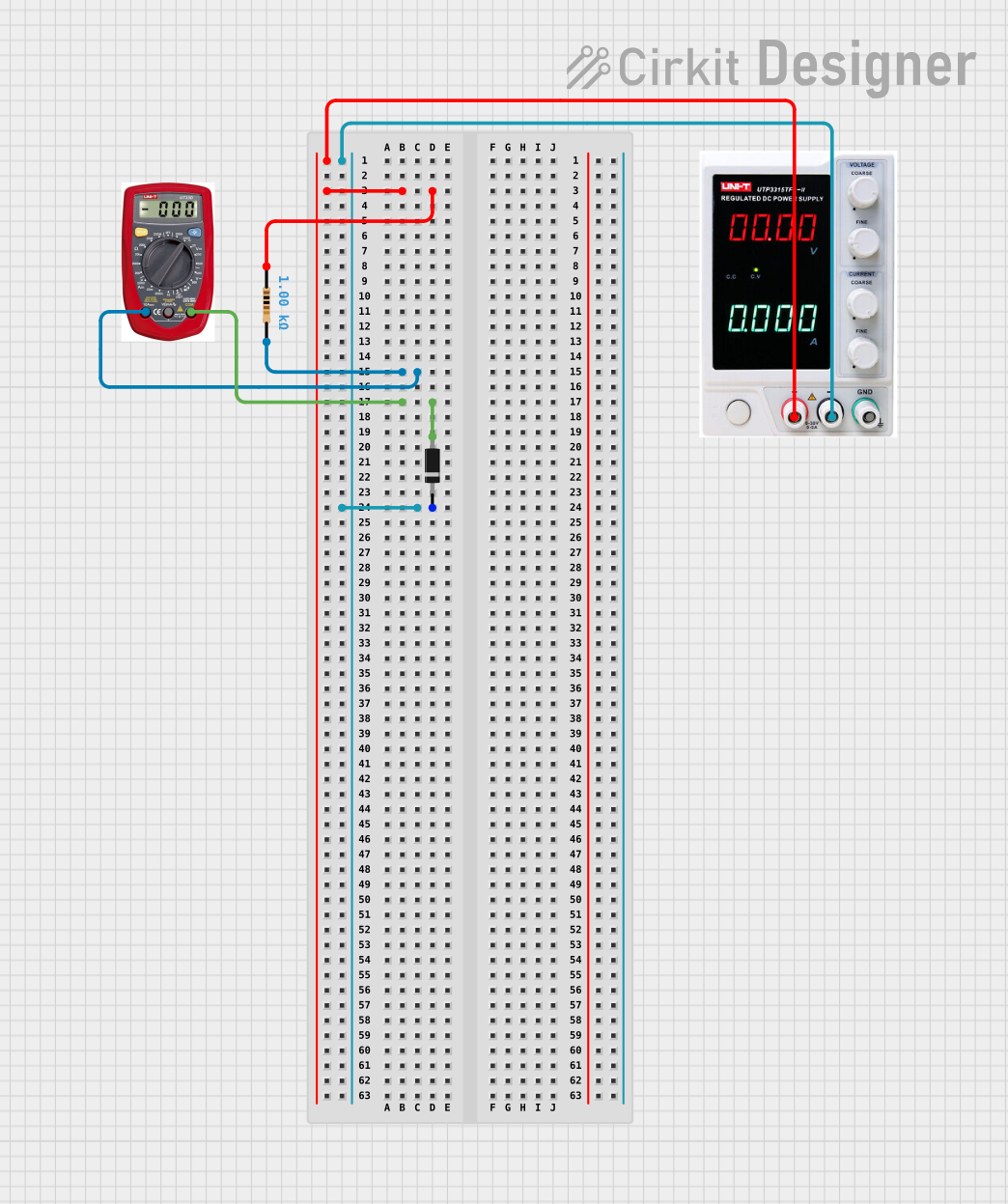 Open Project in Cirkit Designer
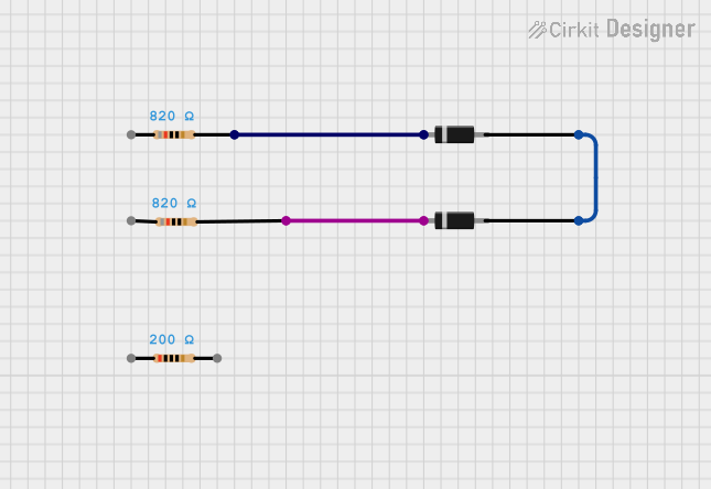 Open Project in Cirkit Designer
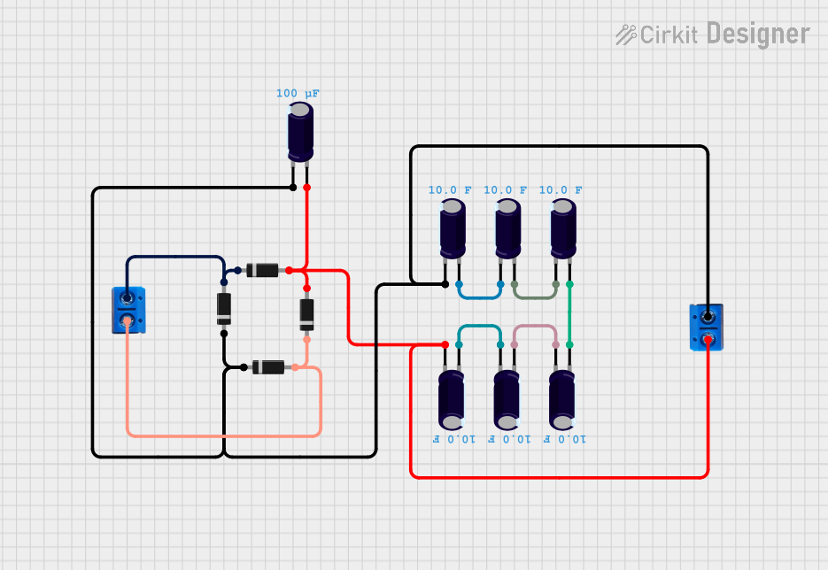 Open Project in Cirkit Designer
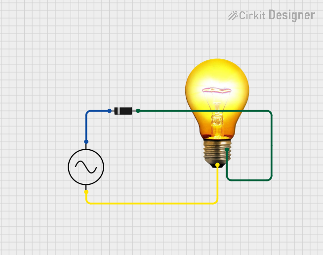 Open Project in Cirkit Designer
Explore Projects Built with Diode
Open Project in Cirkit DesignerOpen Project in Cirkit DesignerOpen Project in Cirkit DesignerOpen Project in Cirkit DesignerCommon Applications and Use Cases
- Rectification: Converting AC (alternating current) to DC (direct current) in power supplies.
- Signal Demodulation: Extracting information from modulated signals in communication systems.
- Voltage Regulation: Stabilizing voltage levels in circuits.
- Circuit Protection: Preventing reverse polarity damage in sensitive components.
- LEDs: Light-emitting diodes are specialized diodes used for illumination and indicators.
Technical Specifications
Below are the general technical specifications for a standard silicon diode (e.g., 1N4007). Specifications may vary depending on the specific diode type.
Key Technical Details
- Forward Voltage Drop (Vf): ~0.7V (silicon diode), ~0.3V (germanium diode)
- Maximum Reverse Voltage (Vr): 1000V (for 1N4007)
- Maximum Forward Current (If): 1A (for 1N4007)
- Power Dissipation: Typically 3W
- Reverse Leakage Current (Ir): ~5µA at Vr max
- Operating Temperature Range: -65°C to +150°C
Pin Configuration and Descriptions
Diodes have two terminals: Anode and Cathode. The cathode is typically marked with a band on the diode body.
| Pin Name | Description | Symbol |
|---|---|---|
| Anode | Positive terminal; current enters here when forward-biased. | A |
| Cathode | Negative terminal; current exits here when forward-biased. | K |
Usage Instructions
How to Use the Diode in a Circuit
- Identify the Terminals: Locate the cathode (marked with a band) and the anode.
- Connect in Forward Bias:
- Connect the anode to the positive voltage source.
- Connect the cathode to the negative or ground.
- Reverse Bias for Blocking:
- Connect the cathode to the positive voltage source.
- Connect the anode to the negative or ground. In this configuration, the diode blocks current flow.
- Use a Current-Limiting Resistor: When using a diode in series with an LED or other components, include a resistor to limit current and prevent damage.
Important Considerations and Best Practices
- Voltage Ratings: Ensure the diode's reverse voltage rating exceeds the maximum voltage in your circuit.
- Current Ratings: Verify that the diode can handle the maximum current in your application.
- Heat Dissipation: For high-power applications, consider heat sinks or diodes with higher power ratings.
- Polarity: Always check the orientation of the diode before powering the circuit.
Example: Using a Diode with an Arduino UNO
Below is an example of using a diode to protect an Arduino UNO from reverse polarity.
/*
 * This example demonstrates how to use a diode to protect an Arduino UNO
 * from reverse polarity. The diode is placed in series with the power supply.
 */

void setup() {
  // No specific code is required for the diode itself.
  // The diode is a passive component that works automatically.

  pinMode(13, OUTPUT); // Set pin 13 as an output for an LED.
}

void loop() {
  digitalWrite(13, HIGH); // Turn on the LED.
  delay(1000);            // Wait for 1 second.
  digitalWrite(13, LOW);  // Turn off the LED.
  delay(1000);            // Wait for 1 second.
}
Circuit Setup:
- Place a diode (e.g., 1N4007) in series with the Arduino's power supply.
- Connect the anode to the positive terminal of the power source.
- Connect the cathode to the Arduino's VIN pin.
Troubleshooting and FAQs
Common Issues
Diode Not Conducting in Forward Bias:
- Cause: Insufficient forward voltage.
- Solution: Ensure the input voltage exceeds the diode's forward voltage drop (e.g., 0.7V for silicon diodes).
Diode Overheating:
- Cause: Exceeding the diode's current or power rating.
- Solution: Use a diode with a higher current rating or add a heat sink.
Reverse Leakage Current:
- Cause: High reverse voltage near the diode's maximum rating.
- Solution: Use a diode with a higher reverse voltage rating.
Incorrect Polarity:
- Cause: Diode connected in reverse.
- Solution: Verify the orientation of the anode and cathode.
FAQs
Q: Can I use a diode to protect my circuit from reverse polarity?
A: Yes, place the diode in series with the power supply. Ensure the diode's current and voltage ratings match your circuit requirements.Q: What happens if I exceed the diode's reverse voltage rating?
A: The diode may break down and allow current to flow in reverse, potentially damaging the circuit.Q: Can I use a diode to drop voltage in a circuit?
A: Yes, diodes can drop voltage (e.g., ~0.7V for silicon diodes). However, this is not an efficient method for significant voltage regulation.Q: What is the difference between a standard diode and a Zener diode?
A: A standard diode allows current to flow in one direction only, while a Zener diode is designed to conduct in reverse when a specific breakdown voltage is reached, making it useful for voltage regulation.
This concludes the documentation for the diode.