Cirkit Designer
Your all-in-one circuit design IDE
Home /
Component Documentation
How to Use ArduCam Mega: Examples, Pinouts, and Specs
Introduction
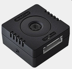
The ArduCam Mega is a high-definition camera module designed for integration with microcontrollers, such as Arduino boards. It is capable of capturing high-quality images and videos, making it an ideal component for a wide range of projects that require visual data input, such as surveillance systems, robotics, environmental monitoring, and DIY electronics.
Explore Projects Built with ArduCam Mega
Arduino UNO-Based Smart Surveillance System with ArduCam Mega, OV7670, and Wi-Fi Connectivity
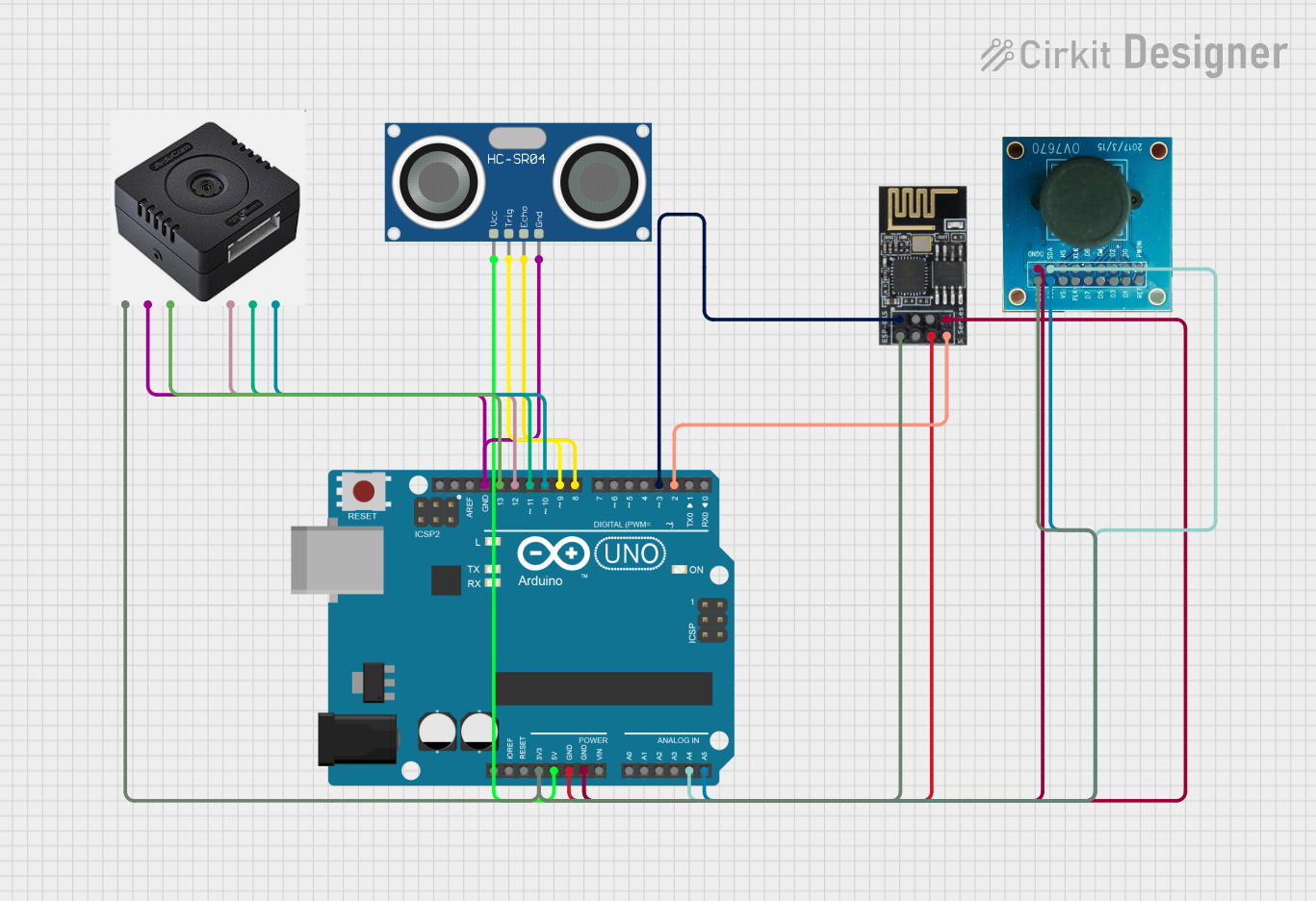
This circuit integrates an Arduino UNO with an ArduCam Mega, an OV7670 camera, an HC-SR04 ultrasonic sensor, and a WiFi module ESP8266-01. The system captures images and distance measurements, processes the data, and transmits it over WiFi to a connected device.
Arduino Mega 2560 and ESP32-CAM Based Smart Sensor System with I2C LCD Display
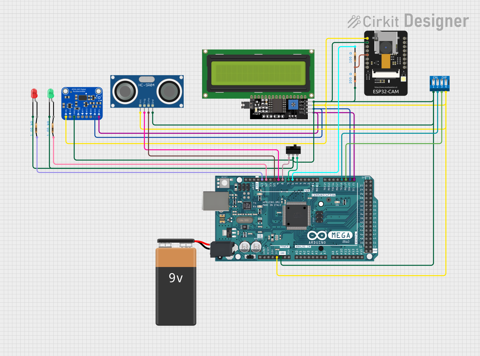
This circuit integrates an Arduino Mega 2560 with various sensors and modules, including an ESP32-CAM, an ADXL345 accelerometer, an HC-SR04 ultrasonic sensor, and an LCD display, to create a multi-functional system. The Arduino Mega serves as the central controller, interfacing with the sensors and display via I2C and digital I/O pins, while the ESP32-CAM provides additional processing and connectivity capabilities.
Arduino and ESP32 Controlled Robotic Arm with Multiple Servo Motors and Ultrasonic Sensor
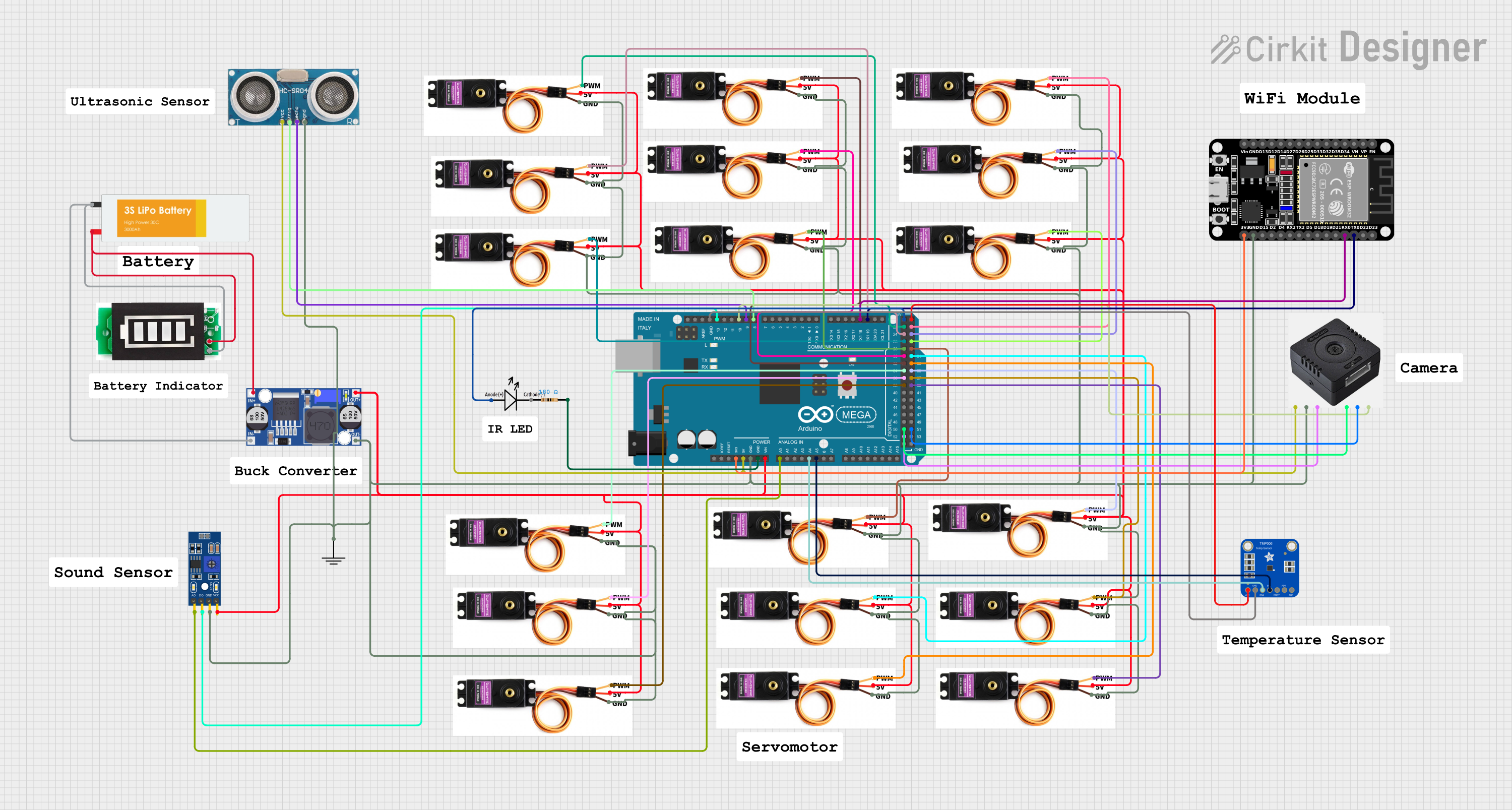
This circuit integrates an Arduino Mega 2560 and an ESP32 to control multiple servo motors, an ultrasonic sensor, and an ArduCam Mega for image capture. The system is powered by a LiPo battery through a buck converter, and it includes additional sensors like a TMP006 thermopile sensor and an LM393 for various measurements.
Dual ESP32-CAM and Arduino Mega 2560 Serial Communication Interface
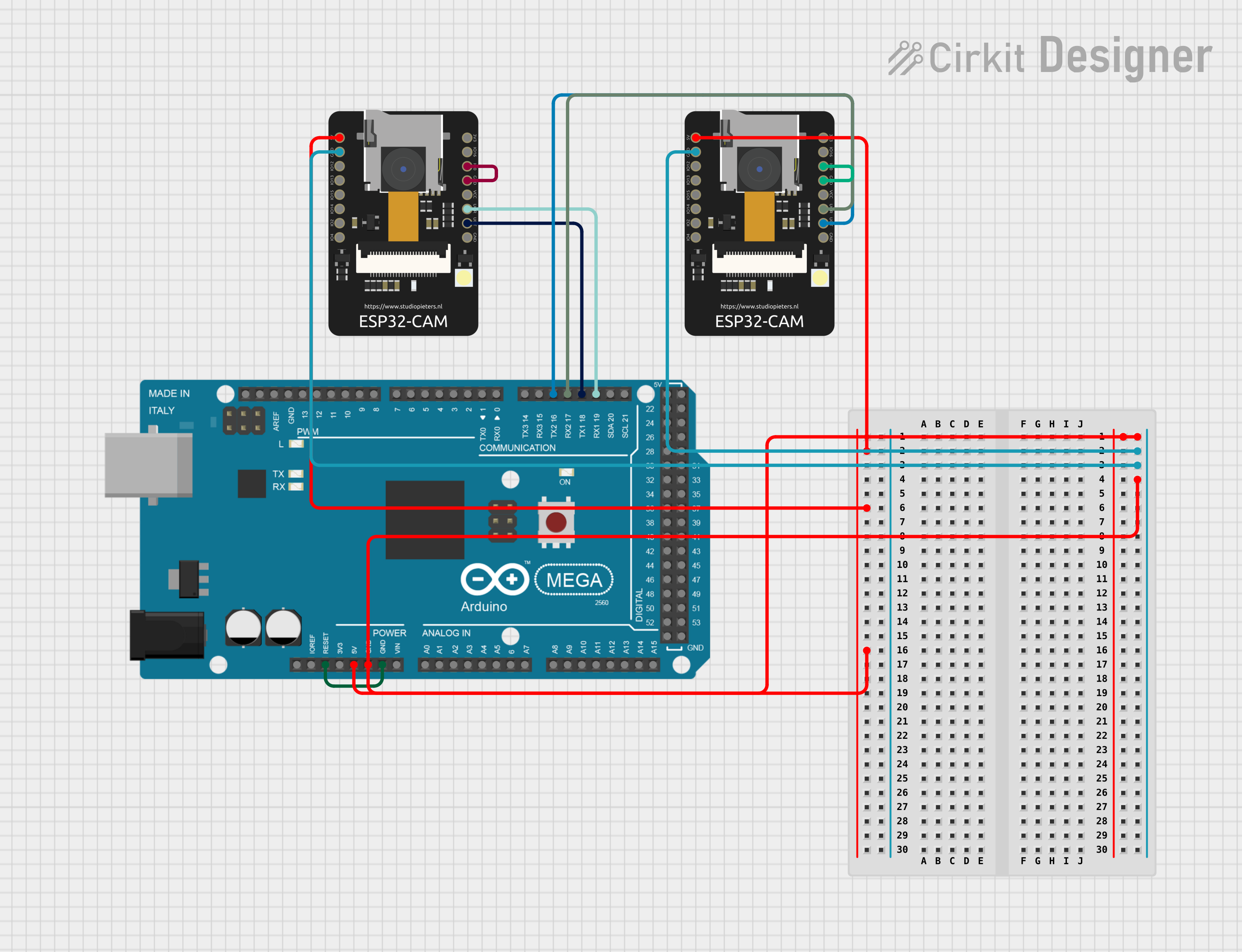
This circuit consists of two ESP32-CAM modules and an Arduino Mega 2560 microcontroller. The ESP32-CAM modules are interfaced with the Arduino Mega 2560 via serial communication, with one module connected to Serial1 (TX1/RX1) and the other to Serial2 (TX2/RX2). The Arduino Mega 2560 runs a sketch that controls an LED on pin D13, turning it on for one second and off for two seconds in a continuous loop.
Explore Projects Built with ArduCam Mega
Arduino UNO-Based Smart Surveillance System with ArduCam Mega, OV7670, and Wi-Fi Connectivity
This circuit integrates an Arduino UNO with an ArduCam Mega, an OV7670 camera, an HC-SR04 ultrasonic sensor, and a WiFi module ESP8266-01. The system captures images and distance measurements, processes the data, and transmits it over WiFi to a connected device.
Arduino Mega 2560 and ESP32-CAM Based Smart Sensor System with I2C LCD Display
This circuit integrates an Arduino Mega 2560 with various sensors and modules, including an ESP32-CAM, an ADXL345 accelerometer, an HC-SR04 ultrasonic sensor, and an LCD display, to create a multi-functional system. The Arduino Mega serves as the central controller, interfacing with the sensors and display via I2C and digital I/O pins, while the ESP32-CAM provides additional processing and connectivity capabilities.
Arduino and ESP32 Controlled Robotic Arm with Multiple Servo Motors and Ultrasonic Sensor
This circuit integrates an Arduino Mega 2560 and an ESP32 to control multiple servo motors, an ultrasonic sensor, and an ArduCam Mega for image capture. The system is powered by a LiPo battery through a buck converter, and it includes additional sensors like a TMP006 thermopile sensor and an LM393 for various measurements.
Dual ESP32-CAM and Arduino Mega 2560 Serial Communication Interface
This circuit consists of two ESP32-CAM modules and an Arduino Mega 2560 microcontroller. The ESP32-CAM modules are interfaced with the Arduino Mega 2560 via serial communication, with one module connected to Serial1 (TX1/RX1) and the other to Serial2 (TX2/RX2). The Arduino Mega 2560 runs a sketch that controls an LED on pin D13, turning it on for one second and off for two seconds in a continuous loop.
Common Applications and Use Cases
- Robotics: Vision for navigation and object recognition.
- Surveillance: Security cameras and motion detection systems.
- Environmental Monitoring: Wildlife observation and time-lapse photography.
- Educational Projects: Teaching camera interfacing and image processing.
- DIY Electronics: Custom-built cameras and creative visual projects.
Technical Specifications
Key Technical Details
- Resolution: Up to 5 megapixels
- Sensor Type: CMOS
- Interface: SPI/I2C
- Operating Voltage: 3.3V - 5V
- Lens Field of View: Adjustable, depending on the lens model
- Frame Rate: Varies with resolution, up to 60fps for lower resolutions
Pin Configuration and Descriptions
| Pin Number | Pin Name | Description |
|---|---|---|
| 1 | VCC | Power supply (3.3V - 5V) |
| 2 | GND | Ground |
| 3 | SCL | I2C clock line / SPI serial clock |
| 4 | SDA | I2C data line / SPI Master Out Slave In |
| 5 | SDO | SPI Master In Slave Out (MISO) |
| 6 | CS | SPI chip select |
| 7 | RESET | Reset pin, active low |
Usage Instructions
How to Use the Component in a Circuit
- Power Supply: Connect the VCC pin to a 3.3V or 5V power source and the GND pin to the ground.
- Data Interface: Connect the SCL and SDA pins for I2C communication or SCL, SDO, and CS for SPI communication to the corresponding pins on your microcontroller.
- Reset: The RESET pin can be connected to a digital pin on the microcontroller to allow software reset of the camera module.
Important Considerations and Best Practices
- Ensure that the power supply is within the specified voltage range to prevent damage.
- Use appropriate pull-up resistors on the I2C lines if they are not included on the module.
- For SPI communication, ensure that the CS pin is driven low before starting any operation and set high after completion.
- Keep the camera lens clean and avoid touching it to maintain image quality.
- When integrating with a microcontroller, ensure that the library and drivers for the ArduCam Mega are correctly installed.
Troubleshooting and FAQs
Common Issues Users Might Face
- No Image Captured: Ensure that the camera module is correctly powered and that all connections are secure. Check that the correct communication protocol (I2C/SPI) is selected and properly configured.
- Poor Image Quality: Clean the lens with a soft, dry cloth. Adjust the focus if the lens supports it. Ensure that the lighting conditions are adequate for the camera sensor.
- Communication Errors: Verify that the wiring is correct and that there are no loose connections. Check that the microcontroller pins are configured correctly for the chosen communication protocol.
Solutions and Tips for Troubleshooting
- Double-check the wiring against the pin configuration table.
- Use example sketches to test basic functionality before integrating into a larger project.
- Consult the ArduCam Mega forums and community for support and advice.
Relevant Code for Arduino UNO
#include <ArduCAM.h>
#include <SPI.h>
#include <Wire.h>

// This is a simple initialization code snippet.
// Replace 'CAMERA_MODEL' with the specific model of your ArduCam Mega.
ArduCAM myCAM(CAMERA_MODEL, CS);

void setup() {
  // Initialize serial communication
  Serial.begin(115200);
  // Initialize the camera
  myCAM.begin();
  // Set the camera resolution
  myCAM.setResolution(ARDUCAM_5MP);
  // Additional configuration as needed
}

void loop() {
  // Capture an image
  myCAM.takePicture();
  // Read the image data
  uint8_t *imageData = myCAM.readPicture();
  // Process the image data as needed
  // ...
}
Note: This code is a basic example to get started with the ArduCam Mega. For a complete implementation, refer to the ArduCam library documentation and examples.
Remember to wrap code comments to limit line length to 80 characters, as shown in the example above. This ensures readability and maintains a clean, professional appearance in the documentation.