Cirkit Designer Logo
Cirkit Designer
Your all-in-one circuit design IDE
Home / 
Component Documentation

How to Use WG901_accelerometer: Examples, Pinouts, and Specs

Image of WG901_accelerometer
Cirkit Designer LogoDesign with WG901_accelerometer in Cirkit Designer

Introduction

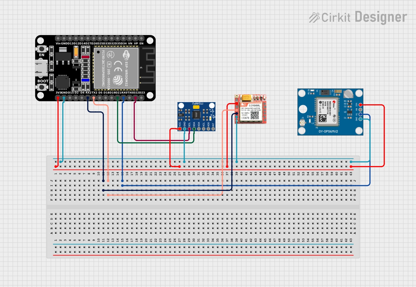
The WG901 accelerometer is a versatile sensor capable of measuring acceleration along multiple axes. It is an essential component in modern electronics, providing critical data for motion detection, orientation, and dynamic acceleration. Common applications include smartphones, wearables, gaming devices, vehicle dynamics, and industrial machinery monitoring.

Explore Projects Built with WG901_accelerometer

Use Cirkit Designer to design, explore, and prototype these projects online. Some projects support real-time simulation. Click "Open Project" to start designing instantly!
Arduino Nano and MPU6050 Based Gesture-Controlled Robotic Arm with Bluetooth Connectivity
Image of Copy of GLOVE ONLY FOR TOGGLE (1): A project utilizing WG901_accelerometer in a practical application
This circuit features multiple MPU6050 accelerometer and gyroscope sensors interfaced with Arduino Nano microcontrollers, likely for capturing motion data. The Arduinos are programmed to read sensor data, calibrate input from potentiometers, and control LEDs. Communication with a Bluetooth module suggests wireless data transmission, possibly to a robotic arm or remote system, based on the motion and flex sensor inputs.
Cirkit Designer LogoOpen Project in Cirkit Designer
Arduino UNO and MPU6050 Accelerometer-Gyroscope Sensor for Motion Tracking
Image of MPU-6050 sensor: A project utilizing WG901_accelerometer in a practical application
This circuit consists of an Arduino UNO microcontroller connected to an MPU6050 accelerometer and gyroscope sensor. The Arduino reads acceleration and gyroscopic data from the MPU6050 via the I2C interface and outputs the sensor readings to the serial monitor.
Cirkit Designer LogoOpen Project in Cirkit Designer
Arduino UNO-Based Impact Detection and GPS Tracking System with GSM Communication
Image of smart helmet: A project utilizing WG901_accelerometer in a practical application
This circuit features an Arduino UNO interfaced with an ADXXL335 accelerometer, a Neo 6M GPS module, and a Sim800l GSM module. The Arduino collects acceleration data and GPS coordinates, and can send SMS alerts or make calls via the GSM module in case of a detected impact or upon receiving a specific SMS command. The system is designed for applications such as vehicle tracking and accident detection.
Cirkit Designer LogoOpen Project in Cirkit Designer
ESP32-Based Accident Detection and GPS Tracking System with GSM Notifications
Image of hello: A project utilizing WG901_accelerometer in a practical application
This circuit features an ESP32 microcontroller interfaced with an MPU6050 accelerometer/gyroscope, a Neo 6M GPS module, and a SIM800L GSM module. The ESP32 communicates with the MPU6050 via I2C (SCL and SDA lines) to detect potential accidents based on acceleration thresholds, with the GPS module providing location data via a serial connection (RX0 and TX0). The SIM800L GSM module is connected to the ESP32 through another serial interface (RX2 and TX2) to send SMS alerts with location information in case of an accident detection.
Cirkit Designer LogoOpen Project in Cirkit Designer

Explore Projects Built with WG901_accelerometer

Use Cirkit Designer to design, explore, and prototype these projects online. Some projects support real-time simulation. Click "Open Project" to start designing instantly!
Image of Copy of GLOVE ONLY FOR TOGGLE (1): A project utilizing WG901_accelerometer in a practical application
Arduino Nano and MPU6050 Based Gesture-Controlled Robotic Arm with Bluetooth Connectivity
This circuit features multiple MPU6050 accelerometer and gyroscope sensors interfaced with Arduino Nano microcontrollers, likely for capturing motion data. The Arduinos are programmed to read sensor data, calibrate input from potentiometers, and control LEDs. Communication with a Bluetooth module suggests wireless data transmission, possibly to a robotic arm or remote system, based on the motion and flex sensor inputs.
Cirkit Designer LogoOpen Project in Cirkit Designer
Image of MPU-6050 sensor: A project utilizing WG901_accelerometer in a practical application
Arduino UNO and MPU6050 Accelerometer-Gyroscope Sensor for Motion Tracking
This circuit consists of an Arduino UNO microcontroller connected to an MPU6050 accelerometer and gyroscope sensor. The Arduino reads acceleration and gyroscopic data from the MPU6050 via the I2C interface and outputs the sensor readings to the serial monitor.
Cirkit Designer LogoOpen Project in Cirkit Designer
Image of smart helmet: A project utilizing WG901_accelerometer in a practical application
Arduino UNO-Based Impact Detection and GPS Tracking System with GSM Communication
This circuit features an Arduino UNO interfaced with an ADXXL335 accelerometer, a Neo 6M GPS module, and a Sim800l GSM module. The Arduino collects acceleration data and GPS coordinates, and can send SMS alerts or make calls via the GSM module in case of a detected impact or upon receiving a specific SMS command. The system is designed for applications such as vehicle tracking and accident detection.
Cirkit Designer LogoOpen Project in Cirkit Designer
Image of hello: A project utilizing WG901_accelerometer in a practical application
ESP32-Based Accident Detection and GPS Tracking System with GSM Notifications
This circuit features an ESP32 microcontroller interfaced with an MPU6050 accelerometer/gyroscope, a Neo 6M GPS module, and a SIM800L GSM module. The ESP32 communicates with the MPU6050 via I2C (SCL and SDA lines) to detect potential accidents based on acceleration thresholds, with the GPS module providing location data via a serial connection (RX0 and TX0). The SIM800L GSM module is connected to the ESP32 through another serial interface (RX2 and TX2) to send SMS alerts with location information in case of an accident detection.
Cirkit Designer LogoOpen Project in Cirkit Designer

Technical Specifications

Key Technical Details

  • Voltage Supply Range: 2.4V to 3.6V
  • Measurement Range: ±2g/±4g/±8g/±16g (selectable)
  • Sensitivity (Selectable): 256 LSB/g @ 2g to 64 LSB/g @ 16g
  • Output Data Rate (ODR): 1 Hz to 5.3 kHz
  • Interface: I2C/SPI (selectable)
  • Operating Temperature: -40°C to +85°C

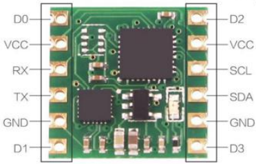
Pin Configuration and Descriptions

Pin Number Pin Name Description
1 VDD Power supply voltage
2 GND Ground
3 SCL/SPC Serial Clock for I2C/SPI Clock
4 SDA/SDI Serial Data for I2C/SPI Data Input
5 SDO SPI Data Output (if SPI mode is selected)
6 CS Chip Select for SPI (active low)
7 INT1 Interrupt 1 output
8 INT2 Interrupt 2 output

Usage Instructions

Integration into a Circuit

  1. Power Supply: Connect VDD to a 2.4V to 3.6V power source and GND to the system ground.
  2. Communication Interface: Choose between I2C or SPI for communication and connect SCL/SPC and SDA/SDI accordingly. If using SPI, also connect SDO and CS.
  3. Interrupts: Optionally, connect INT1 and INT2 to microcontroller interrupt pins for motion detection or data-ready signals.

Best Practices

  • Use decoupling capacitors close to the power pins to filter out noise.
  • Ensure that the I2C/SPI lines have appropriate pull-up resistors.
  • Mount the accelerometer firmly to avoid false readings due to mechanical vibrations.
  • Calibrate the sensor for accurate measurements.

Example Code for Arduino UNO

#include <Wire.h>

// WG901 I2C address (check datasheet for your device's address)
#define WG901_I2C_ADDRESS 0x1D

// Register addresses (refer to the WG901 datasheet)
#define REG_CTRL1 0x20
#define REG_OUT_X 0x29

void setup() {
  Wire.begin(); // Initialize I2C
  Serial.begin(9600); // Start serial communication at 9600 baud

  // Initialize WG901 (set ODR, measurement range, etc.)
  Wire.beginTransmission(WG901_I2C_ADDRESS);
  Wire.write(REG_CTRL1);
  Wire.write(0x57); // Example configuration byte
  Wire.endTransmission();
}

void loop() {
  int16_t xAccel = readAcceleration(REG_OUT_X);
  Serial.print("X-Axis Acceleration: ");
  Serial.println(xAccel);
  delay(100); // Read every 100 milliseconds
}

int16_t readAcceleration(byte regAddress) {
  Wire.beginTransmission(WG901_I2C_ADDRESS);
  Wire.write(regAddress);
  Wire.endTransmission(false);
  Wire.requestFrom(WG901_I2C_ADDRESS, 2, true);

  byte lowByte = Wire.read();
  byte highByte = Wire.read();

  // Combine the two bytes into a 16-bit value and return it
  return (int16_t)((highByte << 8) | lowByte);
}

Troubleshooting and FAQs

Common Issues

  • No Data Output: Ensure that the power supply is within the specified range and that the I2C/SPI connections are correct.
  • Inaccurate Readings: Verify that the accelerometer is properly calibrated and mounted securely.
  • Communication Errors: Check for proper pull-up resistors on the I2C/SPI lines and absence of signal noise.

FAQs

Q: How do I change the measurement range? A: Modify the configuration byte sent to the REG_CTRL1 register to select the desired range.

Q: Can I use both I2C and SPI simultaneously? A: No, you must select one communication protocol and configure the device accordingly.

Q: What is the purpose of the INT1 and INT2 pins? A: These pins can be configured to output interrupt signals for events like data ready, free-fall detection, or motion detection.

Q: How do I interpret the raw acceleration data? A: The raw data needs to be converted using the sensitivity level set by the measurement range. Refer to the datasheet for the conversion formula.

This documentation provides a foundational understanding of the WG901 accelerometer and how to integrate it into electronic projects. For more detailed information, always refer to the manufacturer's datasheet.