How to Use AUDIO PCB: Examples, Pinouts, and Specs
Introduction
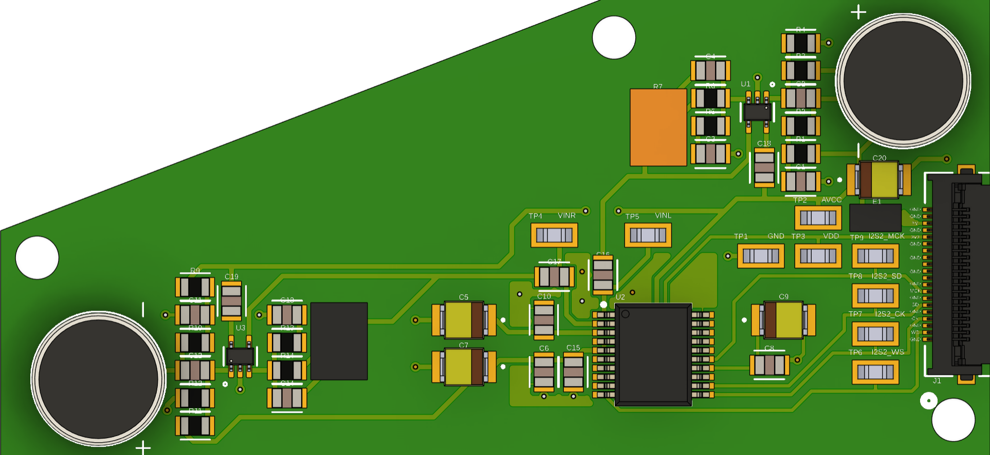
The AUDIO PCB, manufactured by Whistful Whistles, is a printed circuit board specifically designed for audio applications. It serves as a platform for integrating and connecting various audio components, such as amplifiers, mixers, and signal processors. This PCB is engineered to ensure high-quality audio signal transmission with minimal noise and distortion, making it ideal for professional audio systems, home theaters, and DIY audio projects.
Explore Projects Built with AUDIO PCB
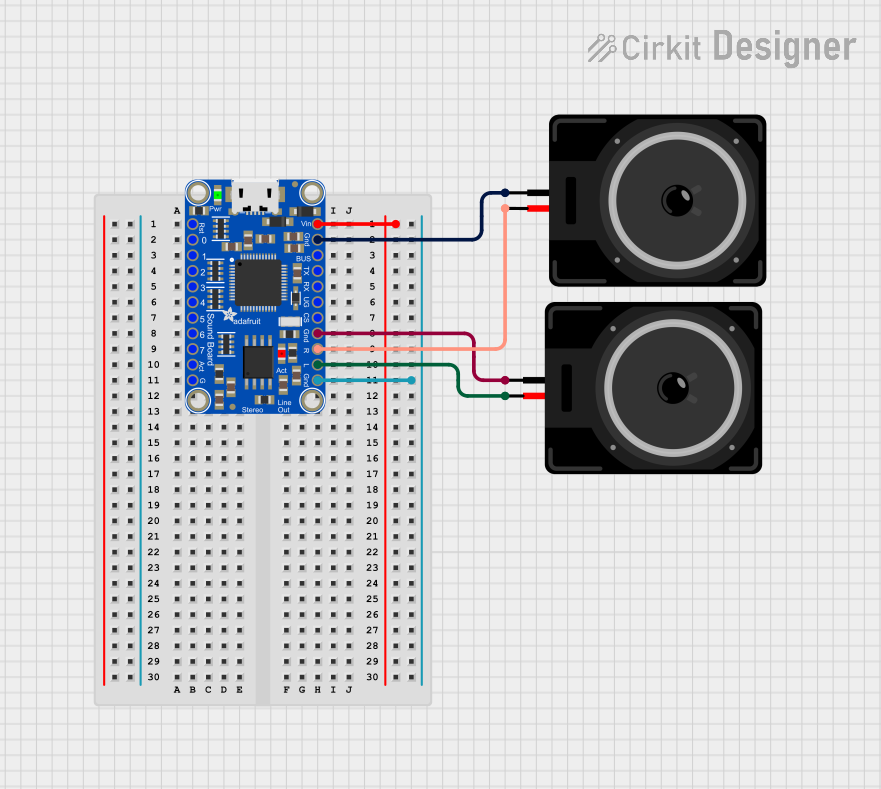
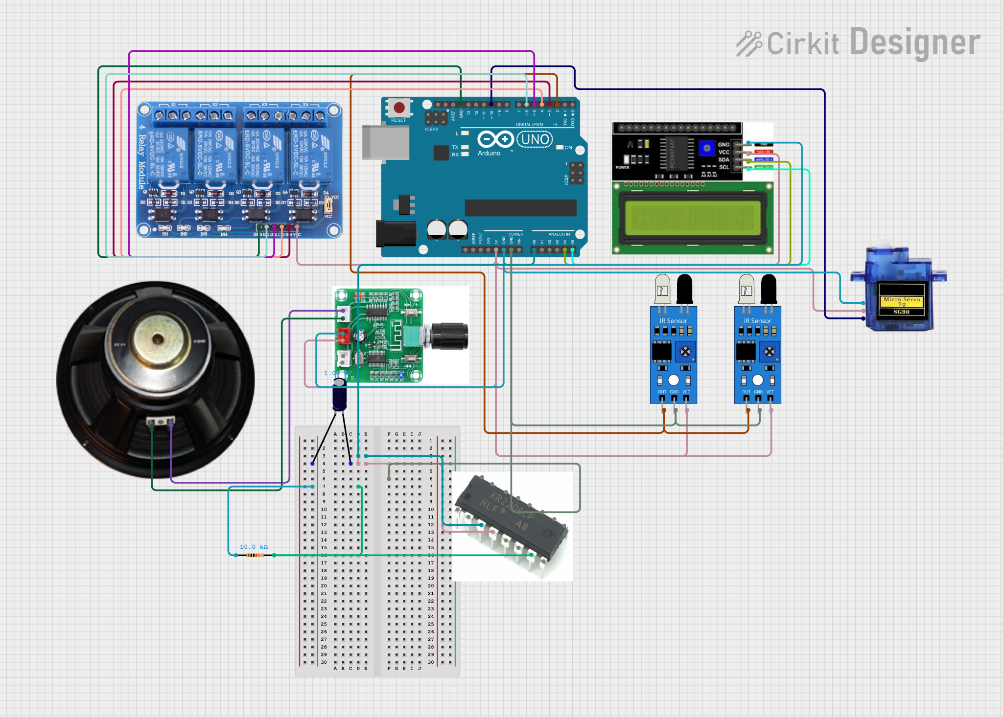
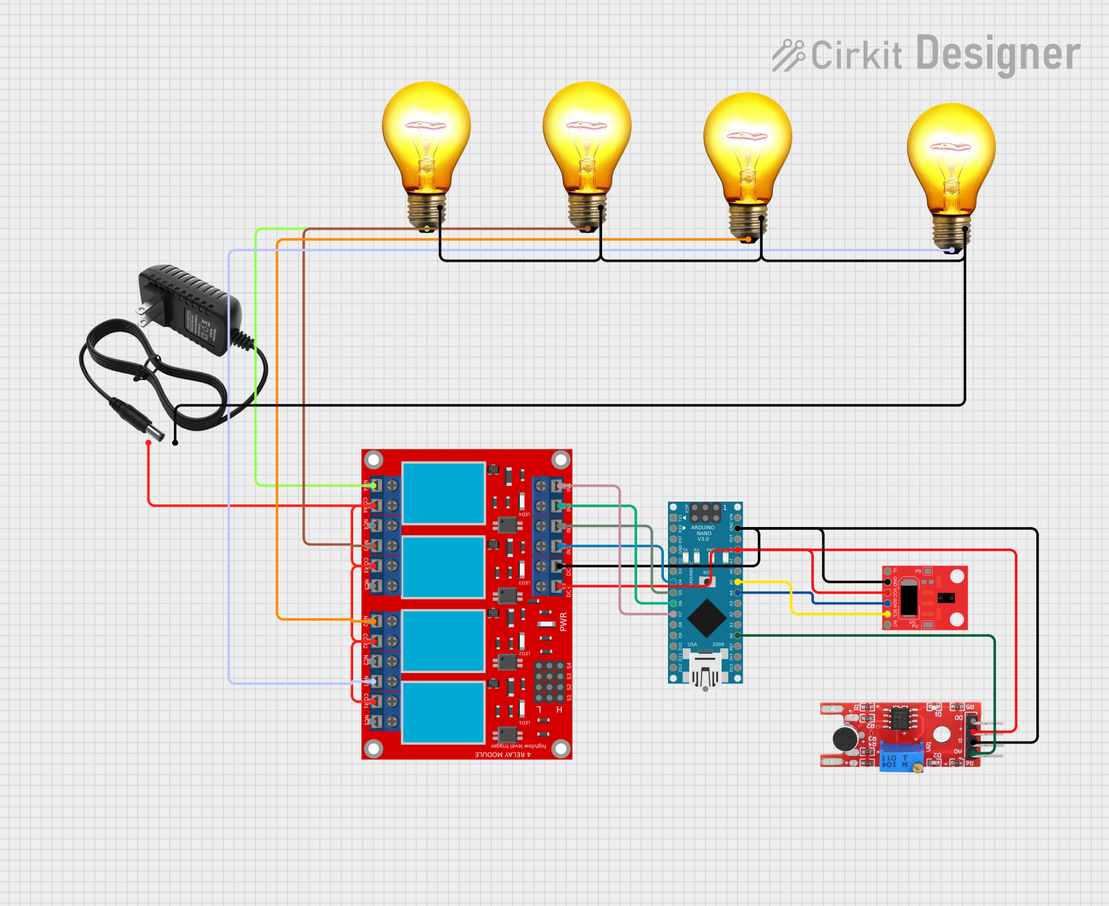

Explore Projects Built with AUDIO PCB
Common Applications and Use Cases
- Audio amplifiers for home or professional use
- Signal processing and mixing boards
- DIY audio projects and prototyping
- Home theater systems
- Musical instrument audio systems
Technical Specifications
The AUDIO PCB is designed to meet the needs of audio enthusiasts and professionals. Below are the key technical details:
General Specifications
| Parameter | Value |
|---|---|
| Manufacturer | Whistful Whistles |
| PCB Material | FR4 (Flame Retardant) |
| PCB Thickness | 1.6 mm |
| Copper Thickness | 1 oz/ft² |
| Number of Layers | 2 |
| Operating Voltage Range | 5V to 24V |
| Maximum Current | 2A |
| Impedance Control | Yes |
| Audio Signal Noise | < 0.01% THD (Total Harmonic Distortion) |
Pin Configuration and Descriptions
The AUDIO PCB includes multiple connectors and terminals for interfacing with audio components. Below is a description of the key pins and connectors:
Input/Output Terminals
| Pin/Connector Name | Type | Description |
|---|---|---|
| IN_L | Input | Left channel audio input |
| IN_R | Input | Right channel audio input |
| OUT_L | Output | Left channel audio output |
| OUT_R | Output | Right channel audio output |
| GND | Ground | Ground connection for the circuit |
| VCC | Power | Power supply input (5V to 24V) |
Control Pins
| Pin Name | Type | Description |
|---|---|---|
| MUTE | Control | Mutes the audio output when pulled HIGH |
| GAIN_SEL | Control | Selects the gain level for the amplifier circuit |
| PWR_EN | Control | Enables or disables power to the PCB |
Usage Instructions
The AUDIO PCB is straightforward to use and can be integrated into a variety of audio systems. Follow the steps below to ensure proper operation:
Step 1: Power Supply
- Connect a DC power supply (5V to 24V) to the
VCCandGNDterminals. - Ensure the power supply can provide sufficient current (up to 2A) for your application.
Step 2: Audio Input
- Connect the left and right audio input signals to the
IN_LandIN_Rterminals, respectively. - Use shielded cables to minimize noise and interference.
Step 3: Audio Output
- Connect the left and right audio output terminals (
OUT_LandOUT_R) to your speakers, headphones, or other audio devices. - Ensure the connected devices are compatible with the output signal levels.
Step 4: Control Pins (Optional)
- Use the
MUTEpin to mute the audio output. Pull the pin HIGH to activate mute mode. - Adjust the gain level using the
GAIN_SELpin. Refer to the manufacturer's datasheet for specific gain settings. - Use the
PWR_ENpin to enable or disable power to the PCB.
Example: Connecting to an Arduino UNO
The AUDIO PCB can be controlled using an Arduino UNO for advanced applications. Below is an example code snippet to control the MUTE and GAIN_SEL pins:
// Define pin connections
const int mutePin = 7;      // Connect to the MUTE pin on the AUDIO PCB
const int gainSelPin = 8;   // Connect to the GAIN_SEL pin on the AUDIO PCB

void setup() {
  // Initialize pins as outputs
  pinMode(mutePin, OUTPUT);
  pinMode(gainSelPin, OUTPUT);

  // Set initial states
  digitalWrite(mutePin, LOW);  // Ensure audio is not muted
  digitalWrite(gainSelPin, LOW); // Set default gain level
}

void loop() {
  // Example: Mute audio for 5 seconds, then unmute
  digitalWrite(mutePin, HIGH);  // Mute audio
  delay(5000);                  // Wait for 5 seconds
  digitalWrite(mutePin, LOW);   // Unmute audio

  // Example: Toggle gain level every 10 seconds
  digitalWrite(gainSelPin, HIGH); // Set higher gain
  delay(10000);                   // Wait for 10 seconds
  digitalWrite(gainSelPin, LOW);  // Set lower gain
  delay(10000);                   // Wait for 10 seconds
}
Best Practices
- Use high-quality, shielded cables for all audio connections to minimize noise.
- Avoid running audio signal cables parallel to power cables to reduce interference.
- Ensure proper grounding to prevent ground loops and hum in the audio signal.
Troubleshooting and FAQs
Common Issues and Solutions
No Audio Output
- Verify that the power supply is connected and providing the correct voltage.
- Check the
MUTEpin state. Ensure it is set to LOW for normal operation. - Confirm that the input and output connections are secure and correctly wired.
Distorted Audio
- Ensure the input signal levels are within the acceptable range for the PCB.
- Check for loose or damaged cables.
- Verify that the gain setting is appropriate for your application.
Excessive Noise or Hum
- Use shielded cables for all audio connections.
- Ensure proper grounding of the PCB and connected devices.
- Avoid placing the PCB near high-frequency or high-power devices.
FAQs
Q: Can the AUDIO PCB handle stereo audio signals?
A: Yes, the AUDIO PCB is designed to handle stereo audio signals with separate left and right channels.
Q: What is the maximum power output of the AUDIO PCB?
A: The AUDIO PCB itself does not amplify signals but facilitates signal routing. The power output depends on the connected amplifier.
Q: Can I use the AUDIO PCB with a battery-powered system?
A: Yes, as long as the battery provides a stable voltage within the 5V to 24V range and sufficient current.
Q: Is the AUDIO PCB compatible with digital audio signals?
A: No, the AUDIO PCB is designed for analog audio signals only. Use a digital-to-analog converter (DAC) if working with digital audio sources.