How to Use Voltage Regulator: Examples, Pinouts, and Specs
Introduction
A voltage regulator is an essential electronic component that ensures electronic devices receive a constant voltage level, regardless of fluctuations in the input voltage or variations in the load. This stability is crucial for sensitive electronics that require a steady power supply to function correctly. Voltage regulators are widely used in power supplies for computers, consumer electronics, and any device that demands a stable voltage to operate reliably.
Explore Projects Built with Voltage Regulator


Explore Projects Built with Voltage Regulator
Common Applications and Use Cases
- Power supplies for electronic circuits
- Battery chargers
- Automotive electronics to regulate alternator output
- Solar power systems
- Voltage regulation for sensitive equipment like medical devices
Technical Specifications
Key Technical Details
- Input Voltage Range: The range of voltage the regulator can accept.
- Output Voltage: The stable voltage the regulator provides.
- Current Rating: Maximum current the regulator can supply.
- Power Dissipation: The amount of power the regulator can dissipate as heat.
- Efficiency: The ratio of output power to input power, expressed as a percentage.
- Line Regulation: The ability to maintain the output voltage as the input voltage varies.
- Load Regulation: The ability to maintain the output voltage as the load varies.
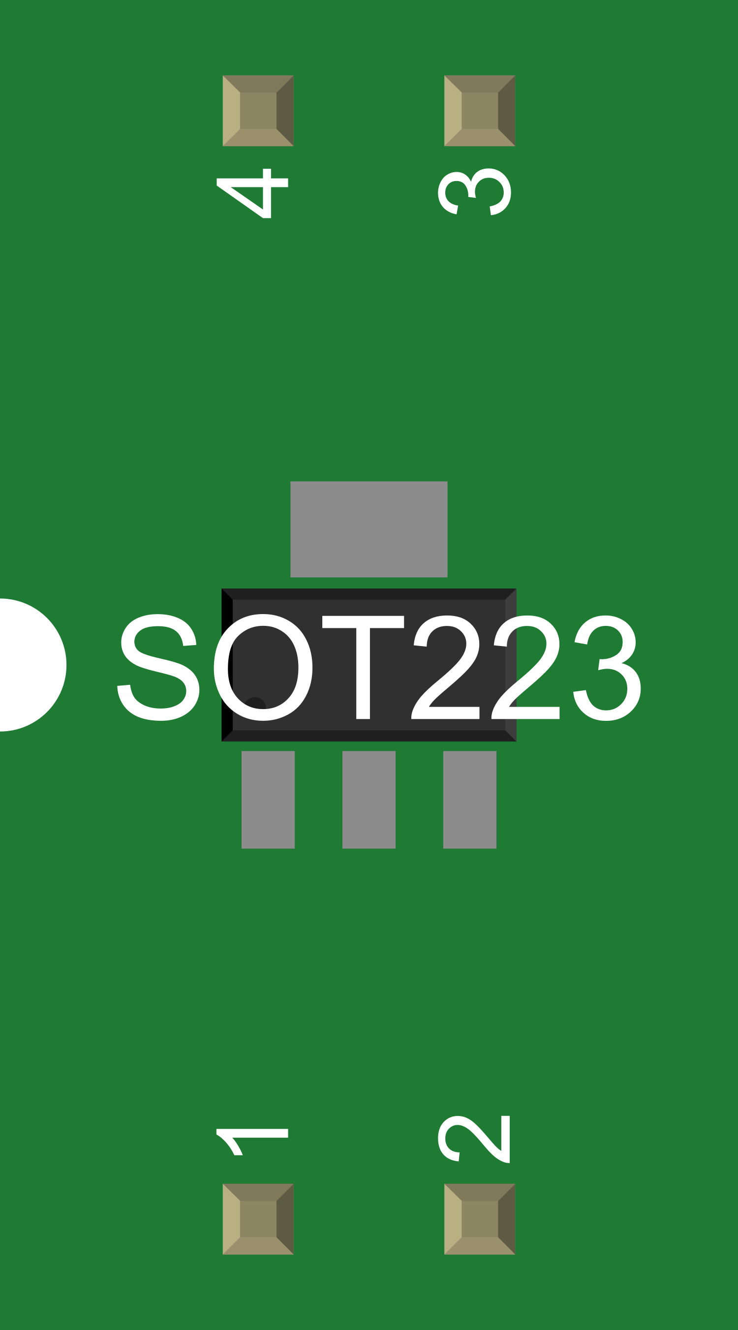
Pin Configuration and Descriptions
| Pin Number | Name | Description |
|---|---|---|
| 1 | IN | Input voltage pin where the unregulated voltage is applied |
| 2 | GND | Ground reference for the regulator |
| 3 | OUT | Output voltage pin providing the regulated voltage |
Usage Instructions
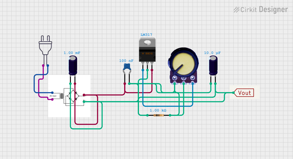
How to Use the Voltage Regulator in a Circuit
- Connect the Input: Apply the unregulated input voltage to the IN pin.
- Grounding: Connect the GND pin to the ground of your circuit.
- Output Voltage: Take the regulated output voltage from the OUT pin.
Important Considerations and Best Practices
- Heat Dissipation: Ensure adequate heat sinking for the regulator, especially when drawing high currents or when there is a significant difference between input and output voltages.
- Capacitors: Place a capacitor close to the input and output pins to filter out voltage spikes and improve stability.
- Input Voltage: Ensure the input voltage is within the specified range for the regulator to prevent damage.
- Current Limit: Do not exceed the current rating of the voltage regulator to avoid overheating and potential failure.
Troubleshooting and FAQs
Common Issues
- Voltage Drop: If the output voltage is lower than expected, check for excessive load or insufficient input voltage.
- Overheating: If the regulator is too hot, improve heat dissipation or check if the current draw is within the specified limit.
- Instability: If the output voltage is unstable, verify the presence and correct value of the input and output capacitors.
Solutions and Tips for Troubleshooting
- Check Connections: Ensure all pins are properly connected and there are no loose connections.
- Measure Input Voltage: Verify that the input voltage is within the specified range for the regulator.
- Inspect Capacitors: Ensure capacitors are correctly rated and properly installed.
- Heat Sink Installation: If overheating persists, consider using a larger heat sink or improving airflow around the regulator.
FAQs
Q: Can I use a voltage regulator to step up voltage? A: No, standard voltage regulators are designed to step down voltage. For stepping up voltage, you would need a boost converter.
Q: What happens if I exceed the current rating of the voltage regulator? A: Exceeding the current rating can lead to overheating and potential failure of the regulator. It may also trigger built-in thermal shutdown mechanisms if available.
Q: How can I increase the efficiency of my voltage regulator? A: To increase efficiency, choose a regulator with a lower dropout voltage or switch to a switching regulator if the application allows.
Example Code for Arduino UNO
Below is an example of how to use a voltage regulator with an Arduino UNO to power an external component that requires a regulated voltage.
// This example assumes the use of a 5V voltage regulator to power an LED.

void setup() {
  pinMode(13, OUTPUT); // Set the built-in LED as an output
}

void loop() {
  digitalWrite(13, HIGH); // Turn on the LED
  delay(1000);            // Wait for 1 second
  digitalWrite(13, LOW);  // Turn off the LED
  delay(1000);            // Wait for 1 second
}

// Note: Connect the output of the voltage regulator to the anode of the LED
// and the cathode to the ground with a suitable current-limiting resistor.
// The input of the voltage regulator should be connected to a voltage source
// higher than 5V (within the specified input range) and the ground to the
// common ground of the circuit.
Remember to comment your code adequately for clarity and maintainability, keeping in mind the 80-character line length limit for comments.