How to Use Stepperonline CL57T Closed Loop Stepper Driver: Examples, Pinouts, and Specs
Introduction
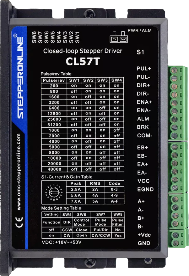
The Stepperonline CL57T is a high-performance closed loop stepper driver that offers precise control over stepper motors. It utilizes encoder feedback to ensure accurate positioning and motion control, making it ideal for applications that require high precision and reliability. Common applications include CNC machines, 3D printers, robotics, and automation systems.
Explore Projects Built with Stepperonline CL57T Closed Loop Stepper Driver
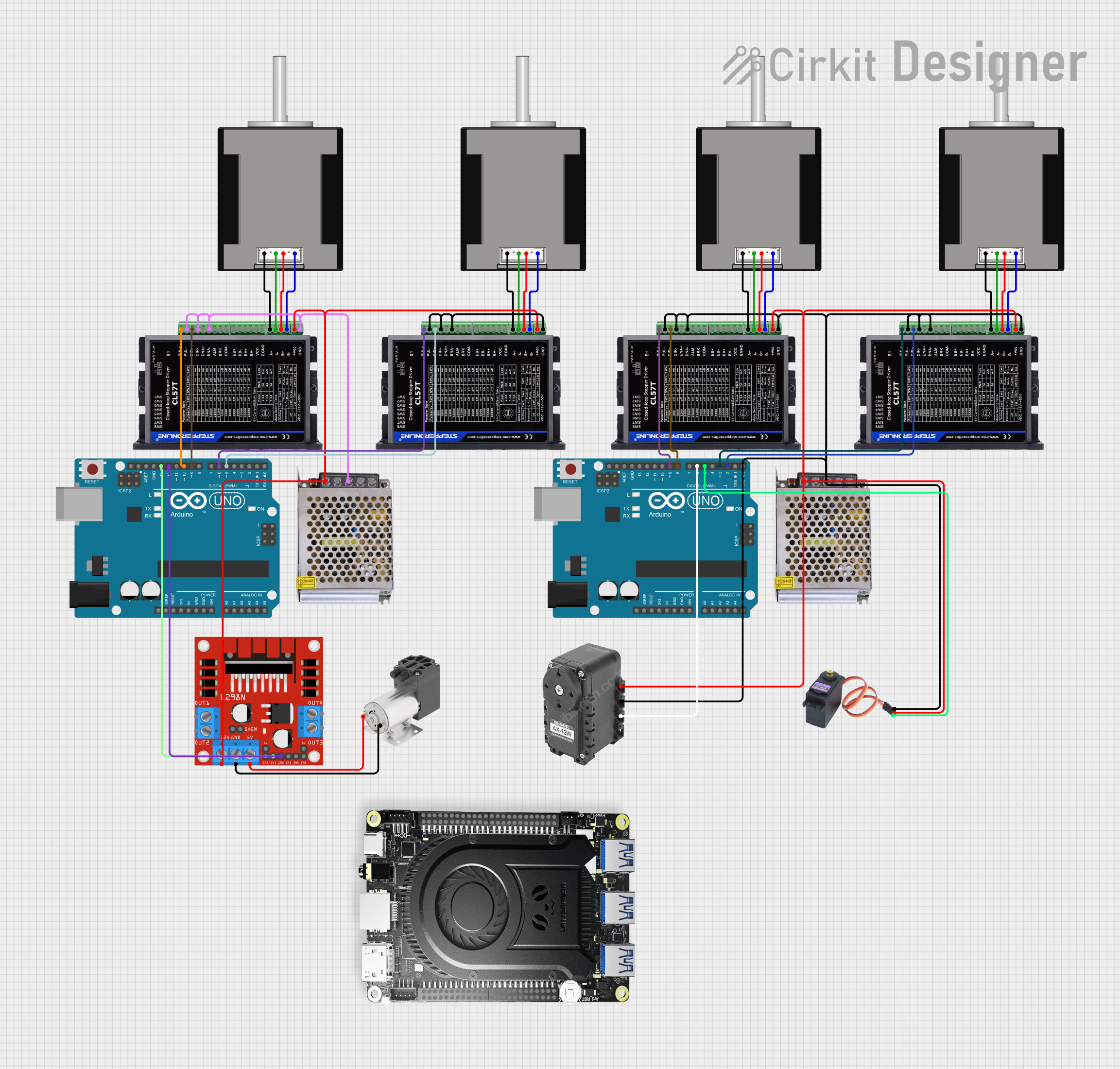

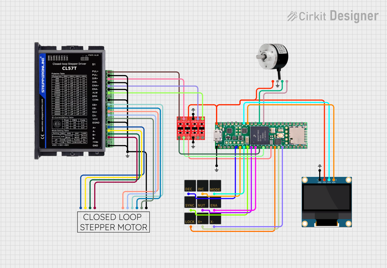
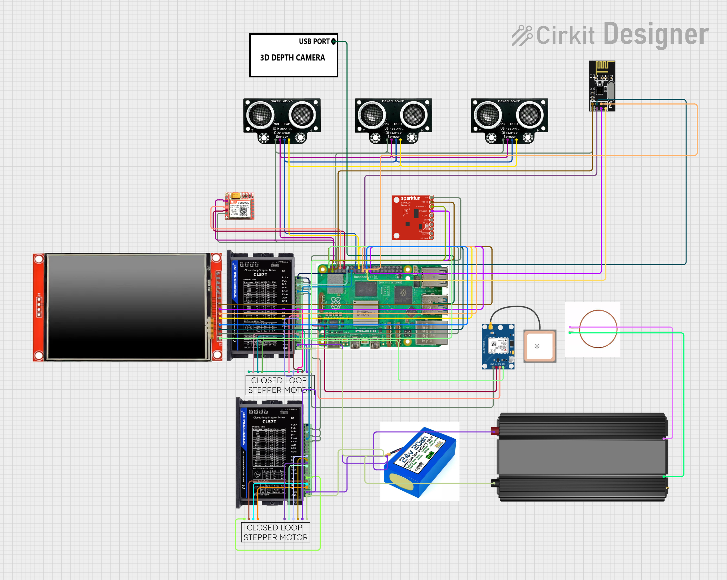
Explore Projects Built with Stepperonline CL57T Closed Loop Stepper Driver
Technical Specifications
Key Technical Details
- Input Voltage: 24-50 VDC
- Output Current: 0.6 - 8.3 A
- Pulse Input Frequency: 0-200 kHz
- Encoder Feedback: 1000 line incremental encoder
- Protection: Over-voltage, under-voltage, over-current, and motor stall protection
Pin Configuration and Descriptions
| Pin No. | Signal Name | Description |
|---|---|---|
| 1 | PUL+ | Pulse signal: In single pulse (pulse/direction) mode, this input represents pulse signal, active on the rising edge. |
| 2 | PUL- | Connected to the negative side of the pulse signal. |
| 3 | DIR+ | Direction signal: This signal is used to change the motor direction. |
| 4 | DIR- | Connected to the negative side of the direction signal. |
| 5 | ENA+ | Enable signal: This signal is used to enable or disable the driver. Active low. |
| 6 | ENA- | Connected to the negative side of the enable signal. |
| 7 | ALM+ | Alarm signal: This output signal indicates that an error has occurred. |
| 8 | ALM- | Connected to the negative side of the alarm signal. |
Usage Instructions
How to Use the Component in a Circuit
- Power Supply: Connect a DC power supply within the range of 24-50 VDC to the driver. Ensure that the power supply can provide sufficient current for the motor.
- Motor Connection: Connect the stepper motor to the driver. Pay attention to the wiring sequence and make sure it matches the driver's phase outputs.
- Encoder Feedback: Connect the encoder lines from the motor to the driver, ensuring proper alignment of signal lines.
- Control Signals: Connect the PUL+, PUL-, DIR+, and DIR- to the respective control outputs from your motion controller or microcontroller (e.g., Arduino).
- Enable Signal: The ENA+ and ENA- can be connected to a switch or controller output to enable or disable the driver as needed.
Important Considerations and Best Practices
- Heat Dissipation: Ensure that the driver is mounted on a heat sink or in a well-ventilated area to prevent overheating.
- Wiring: Use shielded cables for connections, especially for the encoder signals, to minimize interference.
- Settings: Adjust the current settings according to the motor specifications to prevent damage.
- Power Sequence: Always turn on the power supply to the driver before sending control signals to avoid potential damage.
Troubleshooting and FAQs
Common Issues
- Motor Not Turning: Check power supply, connections, and settings. Ensure that the enable signal is active.
- Inaccurate Positioning: Verify encoder connections and settings. Check for mechanical obstructions or load issues.
- Overheating: Ensure proper heat dissipation and check if the current settings are too high.
Solutions and Tips for Troubleshooting
- No Movement: Confirm that the alarm signal is not active, indicating an error state. Reset the driver if necessary.
- Noise or Vibration: Adjust the microstepping settings and current limits to match the motor's specifications.
- Error Codes: Refer to the manufacturer's manual for specific error codes and their meanings.
FAQs
Q: Can I use the CL57T driver with any stepper motor? A: The CL57T is compatible with most stepper motors, but it is essential to match the driver's voltage and current ratings with the motor's specifications.
Q: How do I adjust the current settings on the CL57T? A: Current settings can be adjusted via the onboard dip switches or potentiometer, depending on the model. Refer to the manufacturer's documentation for detailed instructions.
Q: What should I do if the driver overheats? A: Turn off the power immediately, allow the driver to cool down, and check for proper heat dissipation methods. Adjust the current settings if they are set too high.
Example Arduino Code
// Example code to control a stepper motor with the CL57T driver using an Arduino UNO
#define PUL_PIN 2 // Define the pin used for the pulse signal
#define DIR_PIN 3 // Define the pin used for the direction signal
#define ENA_PIN 4 // Define the pin used for the enable signal

void setup() {
  pinMode(PUL_PIN, OUTPUT);
  pinMode(DIR_PIN, OUTPUT);
  pinMode(ENA_PIN, OUTPUT);

  digitalWrite(ENA_PIN, LOW); // Enable the driver
}

void loop() {
  digitalWrite(DIR_PIN, HIGH); // Set motor direction to clockwise
  for (int i = 0; i < 200; i++) { // Move the motor for 200 steps
    digitalWrite(PUL_PIN, HIGH);
    delayMicroseconds(500); // Pulse width should be greater than 2.5μs
    digitalWrite(PUL_PIN, LOW);
    delayMicroseconds(500);
  }

  delay(1000); // Wait for 1 second

  digitalWrite(DIR_PIN, LOW); // Set motor direction to counterclockwise
  for (int i = 0; i < 200; i++) { // Move the motor for 200 steps
    digitalWrite(PUL_PIN, HIGH);
    delayMicroseconds(500);
    digitalWrite(PUL_PIN, LOW);
    delayMicroseconds(500);
  }

  delay(1000); // Wait for 1 second
}
Note: The above code is a simple example to demonstrate basic motor control. In a real-world application, you would need to implement acceleration/deceleration profiles and consider the specific requirements of your application.