How to Use Hx711: Examples, Pinouts, and Specs
Introduction
The HX711 is a precision 24-bit analog-to-digital converter (ADC) designed for weigh scales and industrial control applications. It features low-noise, high-precision signal processing capabilities, making it ideal for reading load cells and other sensors. The HX711 simplifies the process of interfacing with load cells by integrating an amplifier and ADC into a single chip, reducing the need for external components.
Explore Projects Built with Hx711

Explore Projects Built with Hx711
Common Applications and Use Cases
- Digital weigh scales
- Industrial process control
- Force measurement systems
- Pressure sensors
- IoT-based weight monitoring systems
Technical Specifications
The HX711 is designed to provide high accuracy and stability for load cell measurements. Below are its key technical specifications:
| Parameter | Value |
|---|---|
| Supply Voltage | 2.6V to 5.5V |
| Operating Current | < 1.5mA |
| Resolution | 24-bit ADC |
| Input Channels | 2 (Channel A and Channel B) |
| Gain Options | 128 (Channel A), 64 (Channel A), 32 (Channel B) |
| Data Rate | 10 Hz or 80 Hz |
| Input Voltage Range | ±40mV (with gain = 128) |
| Operating Temperature Range | -40°C to +85°C |
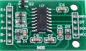
Pin Configuration and Descriptions
The HX711 has 16 pins, but only 10 are typically used in most applications. Below is the pinout and description:
| Pin | Name | Description |
|---|---|---|
| 1 | VCC | Power supply input (2.6V to 5.5V). |
| 2 | GND | Ground connection. |
| 3 | DT | Data output pin for serial communication. |
| 4 | SCK | Serial clock input for data synchronization. |
| 5 | RATE | Data rate selection pin (connect to GND for 10 Hz, VCC for 80 Hz). |
| 6 | VFB | Feedback voltage for internal regulator (optional, typically not used). |
| 7 | VAVDD | Analog power supply (connect to VCC). |
| 8 | VBG | Bandgap reference voltage (optional, typically not used). |
| 9 | IN+ (A) | Positive input for Channel A. |
| 10 | IN- (A) | Negative input for Channel A. |
| 11 | IN+ (B) | Positive input for Channel B. |
| 12 | IN- (B) | Negative input for Channel B. |
Usage Instructions
How to Use the HX711 in a Circuit
- Power Supply: Connect the VCC pin to a 2.6V–5.5V power source and the GND pin to ground.
- Load Cell Connection:
- Connect the load cell's positive and negative signal wires to
IN+ (A)andIN- (A)respectively. - If using Channel B, connect the load cell to
IN+ (B)andIN- (B).
- Connect the load cell's positive and negative signal wires to
- Microcontroller Interface:
- Connect the
DTpin to a digital input pin on your microcontroller. - Connect the
SCKpin to a digital output pin on your microcontroller.
- Connect the
- Data Rate Selection:
- Connect the
RATEpin to GND for a 10 Hz data rate or to VCC for an 80 Hz data rate.
- Connect the
- Gain Selection:
- The gain is set automatically based on the channel used:
- Channel A: Gain of 128 or 64.
- Channel B: Gain of 32.
- The gain is set automatically based on the channel used:
Important Considerations and Best Practices
- Use a stable power supply to minimize noise and improve measurement accuracy.
- Place decoupling capacitors (e.g., 0.1 µF) near the VCC and GND pins to reduce power supply noise.
- Ensure proper shielding and grounding for the load cell wires to avoid interference.
- Use short and thick wires for the load cell connections to reduce resistance and noise.
Example Code for Arduino UNO
Below is an example of how to interface the HX711 with an Arduino UNO to read data from a load cell:
#include "HX711.h" // Include the HX711 library

// Define HX711 pins
#define DT_PIN 3  // Data pin connected to Arduino digital pin 3
#define SCK_PIN 2 // Clock pin connected to Arduino digital pin 2

HX711 scale; // Create an instance of the HX711 class

void setup() {
  Serial.begin(9600); // Initialize serial communication at 9600 baud
  scale.begin(DT_PIN, SCK_PIN); // Initialize the HX711 with the defined pins
  Serial.println("HX711 initialized. Place weight on the scale.");
}

void loop() {
  if (scale.is_ready()) { // Check if the HX711 is ready to send data
    long reading = scale.get_units(); // Get the weight reading in units
    Serial.print("Weight: ");
    Serial.print(reading);
    Serial.println(" units");
  } else {
    Serial.println("HX711 not ready. Check connections.");
  }
  delay(500); // Wait for 500ms before the next reading
}
Notes:
- Install the HX711 library in the Arduino IDE before using the code. You can find it in the Library Manager.
- Calibrate the scale using the library's calibration functions to convert raw units into meaningful weight measurements.
Troubleshooting and FAQs
Common Issues and Solutions
No Data Output:
- Cause: Loose or incorrect wiring.
- Solution: Double-check all connections, especially the
DTandSCKpins.
Unstable Readings:
- Cause: Electrical noise or unstable power supply.
- Solution: Use decoupling capacitors and ensure a stable power source.
Incorrect Weight Measurements:
- Cause: Improper calibration.
- Solution: Perform a proper calibration using known weights.
HX711 Not Ready:
- Cause: Faulty module or incorrect wiring.
- Solution: Replace the HX711 module and verify connections.
FAQs
Q1: Can I use the HX711 with a 3.3V microcontroller?
A1: Yes, the HX711 operates with a supply voltage as low as 2.6V, making it compatible with 3.3V systems.
Q2: How do I calibrate the HX711?
A2: Use the calibration functions provided in the HX711 library. Place a known weight on the load cell and adjust the calibration factor accordingly.
Q3: Can I use both channels (A and B) simultaneously?
A3: Yes, but note that Channel A has higher precision due to its higher gain options (128 and 64) compared to Channel B (gain of 32).
Q4: What is the maximum weight the HX711 can measure?
A4: The maximum weight depends on the load cell used. The HX711 itself does not impose a weight limit but converts the load cell's output into digital data.
Q5: How do I reduce noise in the readings?
A5: Use proper shielding, grounding, and decoupling capacitors. Additionally, average multiple readings to filter out noise.