Cirkit Designer Logo
Cirkit Designer
Your all-in-one circuit design IDE
Home / 
Component Documentation

How to Use DPDT Relay: Examples, Pinouts, and Specs

Image of DPDT Relay
Cirkit Designer LogoDesign with DPDT Relay in Cirkit Designer

Introduction

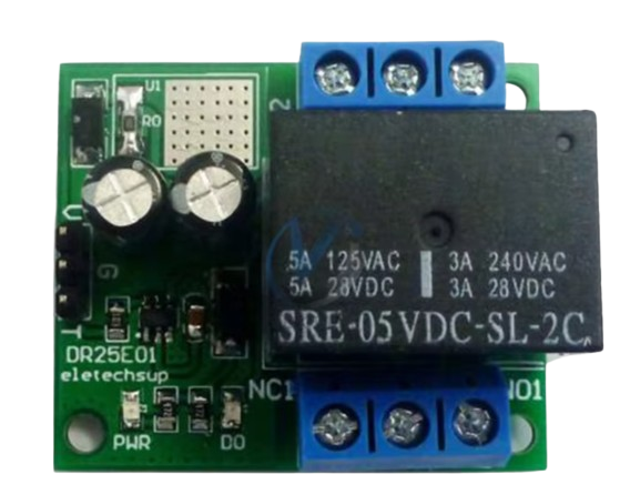
A DPDT (Double-Pole, Double-Throw) Relay is an electromagnetic device designed to control two independent circuits simultaneously, allowing each to be connected to one of two terminals. This relay is commonly used in applications where switching between two power sources or controlling multiple outputs from a single signal is required. Its versatility makes it suitable for a variety of applications, including motor control, signal switching, and power supply management.

Explore Projects Built with DPDT Relay

Use Cirkit Designer to design, explore, and prototype these projects online. Some projects support real-time simulation. Click "Open Project" to start designing instantly!
LDR-Activated Relay Control for Dual Bulb Illumination
Image of automatic headlight control project : A project utilizing DPDT Relay in a practical application
This circuit appears to be a light-activated switch controlling two bulbs using a 5V relay, with an LDR (Light Dependent Resistor) as the sensor. The relay is powered by a 48V to 5V converter, which is switched on by a 12V battery through an SPST toggle switch. The LDR's output is connected to the relay's input, enabling the relay to switch the bulbs on or off based on the ambient light level detected by the LDR.
Cirkit Designer LogoOpen Project in Cirkit Designer
Battery-Powered 4-Channel Relay Control with LED Indicators
Image of RELLAY BOARD TEST: A project utilizing DPDT Relay in a practical application
This circuit consists of a 5V battery powering a 4-channel relay module, which controls four LEDs (red, yellow, green, and blue) through individual resistors. Each relay channel is activated by a corresponding SPST toggle switch, allowing manual control of the LEDs.
Cirkit Designer LogoOpen Project in Cirkit Designer
ESP32 Wi-Fi Controlled Dual Relay Module
Image of esp: A project utilizing DPDT Relay in a practical application
This circuit features an ESP32 microcontroller connected to a two-channel 5V relay module. The ESP32 controls the relay channels via its GPIO pins D23 and D22, allowing it to switch external devices on and off. The relay module is powered by the 3.3V and GND pins of the ESP32.
Cirkit Designer LogoOpen Project in Cirkit Designer
ESP32-Powered 8-Channel Relay Controller with Wi-Fi Connectivity
Image of Olimex ESP32-POE2 4Ch X 2 Switches: A project utilizing DPDT Relay in a practical application
This circuit features an ESP32 microcontroller connected to an 8-channel relay module. The ESP32 controls the relay channels via its GPIO pins, allowing for the switching of external devices or loads through the relays.
Cirkit Designer LogoOpen Project in Cirkit Designer

Explore Projects Built with DPDT Relay

Use Cirkit Designer to design, explore, and prototype these projects online. Some projects support real-time simulation. Click "Open Project" to start designing instantly!
Image of automatic headlight control project : A project utilizing DPDT Relay in a practical application
LDR-Activated Relay Control for Dual Bulb Illumination
This circuit appears to be a light-activated switch controlling two bulbs using a 5V relay, with an LDR (Light Dependent Resistor) as the sensor. The relay is powered by a 48V to 5V converter, which is switched on by a 12V battery through an SPST toggle switch. The LDR's output is connected to the relay's input, enabling the relay to switch the bulbs on or off based on the ambient light level detected by the LDR.
Cirkit Designer LogoOpen Project in Cirkit Designer
Image of RELLAY BOARD TEST: A project utilizing DPDT Relay in a practical application
Battery-Powered 4-Channel Relay Control with LED Indicators
This circuit consists of a 5V battery powering a 4-channel relay module, which controls four LEDs (red, yellow, green, and blue) through individual resistors. Each relay channel is activated by a corresponding SPST toggle switch, allowing manual control of the LEDs.
Cirkit Designer LogoOpen Project in Cirkit Designer
Image of esp: A project utilizing DPDT Relay in a practical application
ESP32 Wi-Fi Controlled Dual Relay Module
This circuit features an ESP32 microcontroller connected to a two-channel 5V relay module. The ESP32 controls the relay channels via its GPIO pins D23 and D22, allowing it to switch external devices on and off. The relay module is powered by the 3.3V and GND pins of the ESP32.
Cirkit Designer LogoOpen Project in Cirkit Designer
Image of Olimex ESP32-POE2 4Ch X 2 Switches: A project utilizing DPDT Relay in a practical application
ESP32-Powered 8-Channel Relay Controller with Wi-Fi Connectivity
This circuit features an ESP32 microcontroller connected to an 8-channel relay module. The ESP32 controls the relay channels via its GPIO pins, allowing for the switching of external devices or loads through the relays.
Cirkit Designer LogoOpen Project in Cirkit Designer

Technical Specifications

General Characteristics

  • Switch Type: Double-Pole, Double-Throw (DPDT)
  • Control Voltage: Typically 5V to 12V DC
  • Contact Rating: Varies by model (e.g., 10A at 250VAC, 10A at 30VDC)
  • Operate Time: Typically 5ms to 20ms
  • Release Time: Typically 5ms to 20ms
  • Operating Temperature: -40°C to 85°C (varies by manufacturer)

Pin Configuration and Descriptions

Pin Number Description Notes
1 Coil End 1 Connect to DC voltage supply
2 Coil End 2 Connect to ground
3 Common Pole 1 Switchable pole for circuit 1
4 Normally Closed (NC) 1 Default connection for circuit 1
5 Normally Open (NO) 1 Activated connection for circuit 1
6 Common Pole 2 Switchable pole for circuit 2
7 Normally Closed (NC) 2 Default connection for circuit 2
8 Normally Open (NO) 2 Activated connection for circuit 2

Usage Instructions

Wiring the DPDT Relay to a Circuit

  1. Connect the coil pins (1 and 2) to your control circuit, ensuring the correct voltage is applied.
  2. Connect the common poles (3 and 6) to the circuits you wish to control.
  3. Wire the Normally Open (NO) and Normally Closed (NC) contacts to the respective outputs for each circuit.

Best Practices

  • Always verify the coil voltage and contact ratings before applying power to the relay.
  • Use a diode across the coil terminals to prevent back EMF when the coil is de-energized.
  • Ensure that all connections are secure to prevent accidental disconnection or short circuits.

Example Circuit with Arduino UNO

// Example code to control a DPDT relay with an Arduino UNO

const int relayPin = 2; // Relay control pin

void setup() {
  pinMode(relayPin, OUTPUT); // Set relay pin as output
}

void loop() {
  digitalWrite(relayPin, HIGH); // Activate the relay
  delay(1000);                  // Wait for 1 second
  digitalWrite(relayPin, LOW);  // Deactivate the relay
  delay(1000);                  // Wait for 1 second
}

Troubleshooting and FAQs

Common Issues

  • Relay not switching: Ensure the control voltage is within the specified range and connections are secure.
  • Contacts not conducting: Check if the contacts are rated for the current and voltage of your circuit.
  • Coil overheating: Verify that the coil voltage matches the supply and is not being driven too hard.

FAQs

Q: Can I use a DPDT relay to switch AC loads? A: Yes, ensure the contact ratings match the requirements of your AC load.

Q: How can I protect the relay from voltage spikes? A: Use a flyback diode across the coil terminals to absorb voltage spikes when the coil is turned off.

Q: Can I control a DPDT relay with a microcontroller? A: Yes, you can control it using a digital output pin, but ensure you have a suitable driver if the coil voltage exceeds the microcontroller's voltage levels.

For further assistance, consult the manufacturer's datasheet specific to the part ID 'dpdt' and contact technical support if necessary.