How to Use scd41_front: Examples, Pinouts, and Specs
Introduction
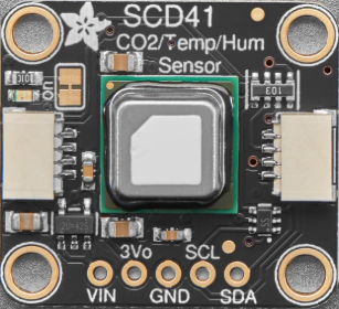
The SCD41 is a digital sensor designed for measuring carbon dioxide (CO2), temperature, and humidity. It employs non-dispersive infrared (NDIR) technology for CO2 detection, ensuring high accuracy and reliability. This compact sensor is ideal for applications requiring precise indoor air quality monitoring, such as HVAC systems, air purifiers, smart home devices, and environmental monitoring systems.
Explore Projects Built with scd41_front


Explore Projects Built with scd41_front
Common Applications
- Indoor air quality monitoring
- HVAC (Heating, Ventilation, and Air Conditioning) systems
- Air purifiers and dehumidifiers
- Smart home and IoT devices
- Environmental monitoring and research
Technical Specifications
The SCD41 sensor offers robust performance and a compact design. Below are its key technical specifications:
| Parameter | Value |
|---|---|
| Measurement Range | CO2: 400–5000 ppm |
| Accuracy (CO2) | ±(40 ppm + 5% of reading) |
| Temperature Range | -10°C to 60°C |
| Humidity Range | 0% to 100% RH (non-condensing) |
| Supply Voltage | 2.4 V to 5.5 V |
| Current Consumption | 2 mA (average), 24 mA (peak) |
| Communication Interface | I2C |
| Dimensions | 10.1 mm × 10.1 mm × 6.5 mm |
Pin Configuration and Descriptions
The SCD41 sensor has a simple pinout for easy integration into circuits. Below is the pin configuration:
| Pin | Name | Description |
|---|---|---|
| 1 | VDD | Power supply (2.4 V to 5.5 V) |
| 2 | GND | Ground |
| 3 | SDA | I2C data line |
| 4 | SCL | I2C clock line |
| 5 | SEL | Address select (connect to GND for default address) |
| 6 | NC | Not connected (leave floating) |
Usage Instructions
How to Use the SCD41 in a Circuit
- Power Supply: Connect the VDD pin to a 3.3 V or 5 V power source and the GND pin to ground.
- I2C Communication: Connect the SDA and SCL pins to the corresponding I2C pins on your microcontroller. Use pull-up resistors (typically 4.7 kΩ) on both lines if not already present.
- Address Selection: If using multiple SCD41 sensors, configure the SEL pin to set a unique I2C address. For a single sensor, connect SEL to GND for the default address.
- Initialization: Use the I2C protocol to initialize the sensor and start measurements. The sensor outputs CO2, temperature, and humidity data.
Important Considerations
- Warm-Up Time: Allow the sensor to warm up for at least 5 seconds after power-up for accurate readings.
- Ventilation: Ensure proper airflow around the sensor for reliable measurements.
- Humidity: Avoid exposing the sensor to condensing environments, as this may affect performance.
- Calibration: The SCD41 features automatic self-calibration. However, periodic manual calibration may be required in environments with consistently high or low CO2 levels.
Example Code for Arduino UNO
Below is an example of how to interface the SCD41 with an Arduino UNO using the I2C protocol. This code uses the Sensirion SCD4x library, which can be installed via the Arduino Library Manager.
#include <Wire.h>
#include <SensirionI2CScd4x.h>

SensirionI2CScd4x scd4x;

void setup() {
  Wire.begin(); // Initialize I2C communication
  Serial.begin(9600); // Start serial communication for debugging

  scd4x.begin(Wire); // Initialize the SCD41 sensor
  uint16_t error;
  char errorMessage[256];

  // Start periodic measurement
  error = scd4x.startPeriodicMeasurement();
  if (error) {
    scd4x.getError(error, errorMessage, sizeof(errorMessage));
    Serial.print("Error starting measurement: ");
    Serial.println(errorMessage);
    while (1); // Halt execution if initialization fails
  }
  Serial.println("SCD41 initialized successfully.");
}

void loop() {
  uint16_t co2;
  float temperature, humidity;
  uint16_t error;
  char errorMessage[256];

  // Read measurement data
  error = scd4x.readMeasurement(co2, temperature, humidity);
  if (error) {
    scd4x.getError(error, errorMessage, sizeof(errorMessage));
    Serial.print("Error reading measurement: ");
    Serial.println(errorMessage);
    delay(1000); // Retry after 1 second
    return;
  }

  // Print sensor data to the serial monitor
  Serial.print("CO2: ");
  Serial.print(co2);
  Serial.print(" ppm, Temperature: ");
  Serial.print(temperature);
  Serial.print(" °C, Humidity: ");
  Serial.print(humidity);
  Serial.println(" %RH");

  delay(2000); // Wait 2 seconds before the next reading
}
Troubleshooting and FAQs
Common Issues and Solutions
No Data from Sensor
- Cause: Incorrect I2C wiring or address mismatch.
- Solution: Verify SDA and SCL connections. Ensure the SEL pin is configured correctly for the desired I2C address.
Inaccurate Readings
- Cause: Insufficient warm-up time or poor ventilation.
- Solution: Allow the sensor to warm up for at least 5 seconds. Ensure proper airflow around the sensor.
Sensor Not Detected
- Cause: Missing pull-up resistors on the I2C lines.
- Solution: Add 4.7 kΩ pull-up resistors to the SDA and SCL lines.
Condensation on Sensor
- Cause: Exposure to high humidity or condensing environments.
- Solution: Avoid placing the sensor in environments where condensation is likely. Use a protective enclosure if necessary.
FAQs
Q: Can the SCD41 operate at 5 V?
A: Yes, the SCD41 supports a supply voltage range of 2.4 V to 5.5 V.Q: Does the sensor require manual calibration?
A: The SCD41 features automatic self-calibration. However, manual calibration may be needed in environments with consistently high or low CO2 levels.Q: What is the default I2C address of the SCD41?
A: The default I2C address is determined by the SEL pin. When SEL is connected to GND, the default address is used.Q: Can I use the SCD41 outdoors?
A: The SCD41 is designed for indoor use. Outdoor use may expose the sensor to extreme conditions, affecting its performance and lifespan.