How to Use RGB led light: Examples, Pinouts, and Specs
Introduction
An RGB LED light is a light-emitting diode capable of emitting red, green, and blue light. By adjusting the intensity of each color, a wide spectrum of colors can be produced. This makes RGB LEDs versatile and widely used in applications requiring dynamic lighting effects.
Explore Projects Built with RGB led light
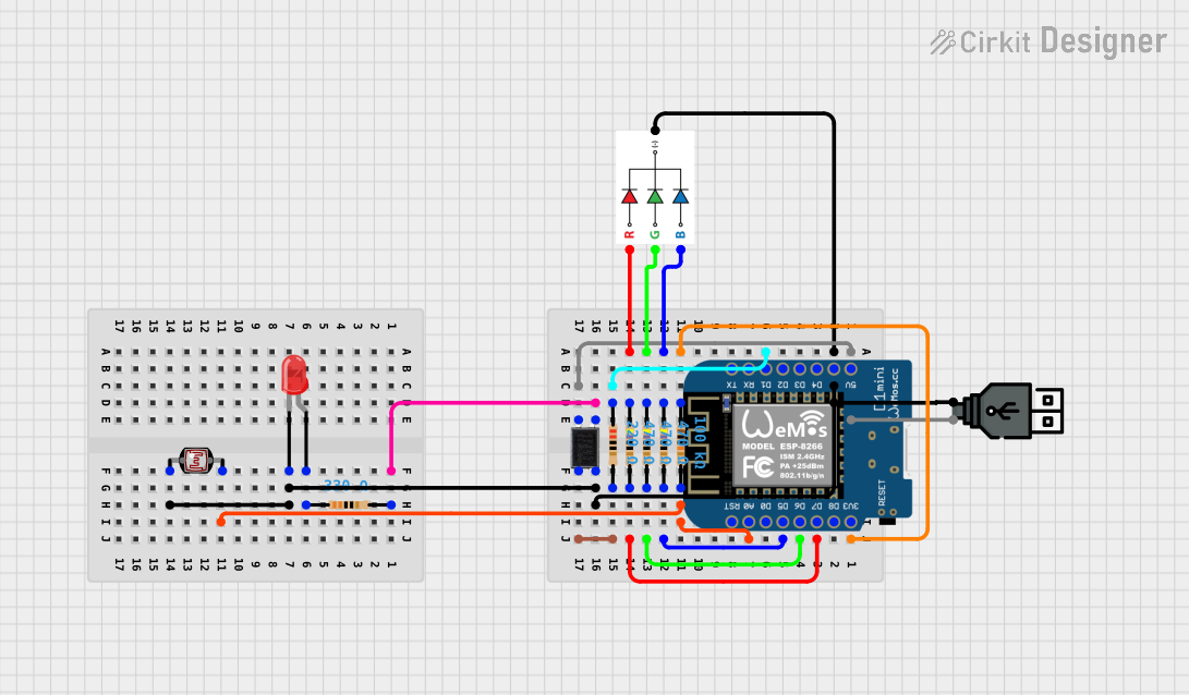

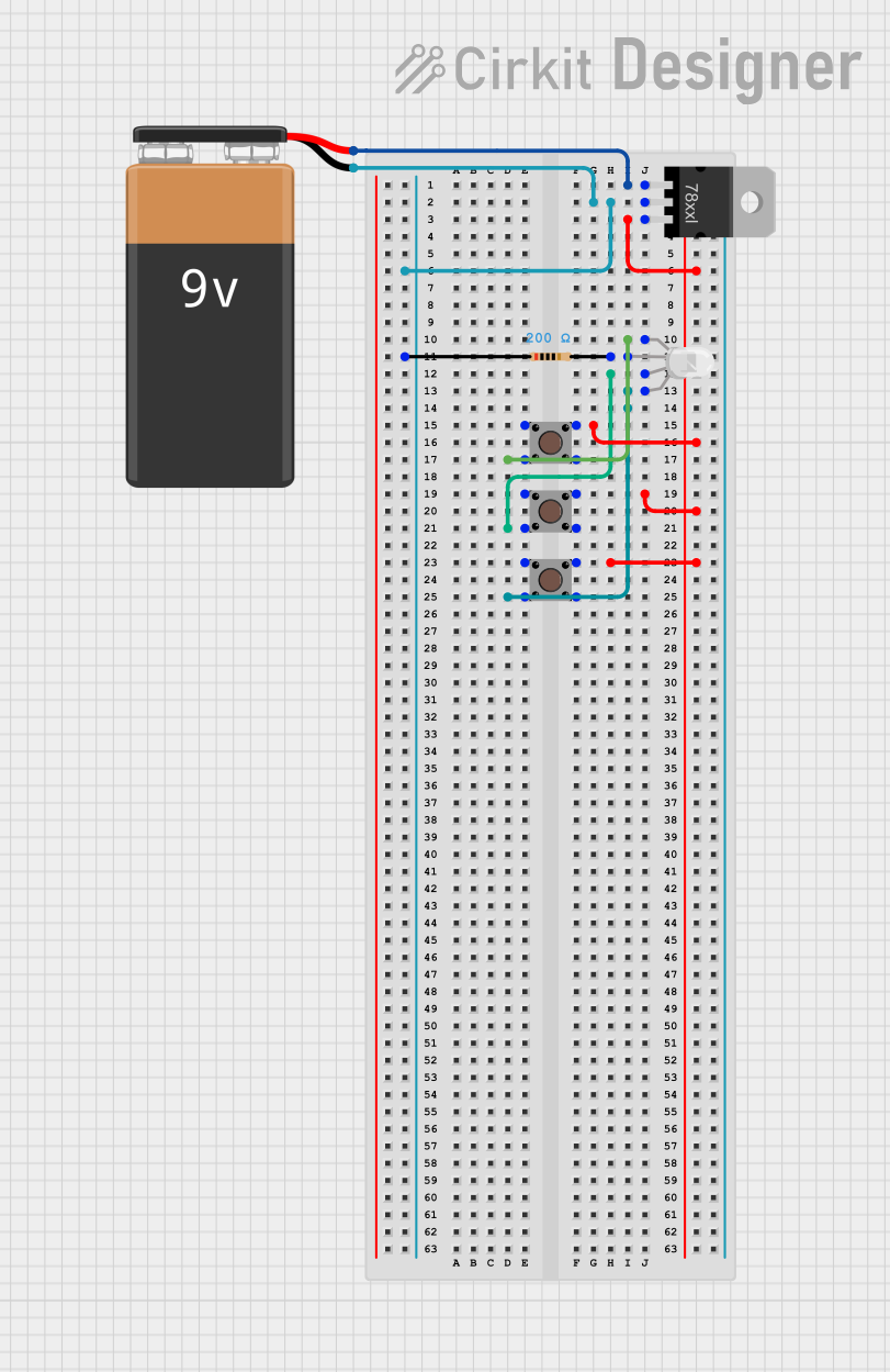
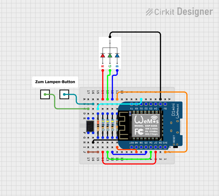
Explore Projects Built with RGB led light
Common Applications and Use Cases
- Decorative lighting and displays
- Status indicators in electronic devices
- Mood lighting and smart home systems
- Gaming peripherals and PC case lighting
- Educational projects and prototyping with microcontrollers
Technical Specifications
Below are the key technical details for a standard common cathode RGB LED. Note that specifications may vary slightly depending on the manufacturer.
| Parameter | Value |
|---|---|
| Forward Voltage (Red) | 1.8V - 2.2V |
| Forward Voltage (Green) | 3.0V - 3.2V |
| Forward Voltage (Blue) | 3.0V - 3.2V |
| Forward Current | 20mA (per color channel) |
| Power Dissipation | 60mW (typical) |
| Viewing Angle | 120° |
| Operating Temperature | -40°C to +85°C |
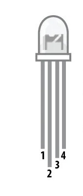
Pin Configuration
RGB LEDs typically have four pins: one for each color (red, green, and blue) and a common pin. The common pin can either be a cathode (connected to ground) or an anode (connected to the power supply). Below is the pinout for a common cathode RGB LED.
| Pin Number | Pin Name | Description |
|---|---|---|
| 1 | Red | Controls the red LED |
| 2 | Common Cathode | Shared ground for all LEDs |
| 3 | Green | Controls the green LED |
| 4 | Blue | Controls the blue LED |
Usage Instructions
How to Use the RGB LED in a Circuit
- Identify the Pins: Use the pinout table above to identify the red, green, blue, and common cathode pins.
- Connect Resistors: To prevent damage, connect a current-limiting resistor (typically 220Ω to 330Ω) in series with each color pin.
- Power the LED: Connect the common cathode pin to ground (GND) and the color pins to a microcontroller or power source through the resistors.
- Control the Colors: Adjust the voltage or use pulse-width modulation (PWM) on the red, green, and blue pins to mix colors.
Example Circuit with Arduino UNO
Below is an example of how to connect and control an RGB LED using an Arduino UNO.
Circuit Connections
- Connect the common cathode pin to the Arduino's GND.
- Connect the red pin to Arduino pin 9 through a 220Ω resistor.
- Connect the green pin to Arduino pin 10 through a 220Ω resistor.
- Connect the blue pin to Arduino pin 11 through a 220Ω resistor.
Arduino Code
// Define the RGB LED pins
const int redPin = 9;   // Pin connected to the red LED
const int greenPin = 10; // Pin connected to the green LED
const int bluePin = 11;  // Pin connected to the blue LED

void setup() {
  // Set the RGB pins as output
  pinMode(redPin, OUTPUT);
  pinMode(greenPin, OUTPUT);
  pinMode(bluePin, OUTPUT);
}

void loop() {
  // Example: Display red color
  analogWrite(redPin, 255);   // Full brightness for red
  analogWrite(greenPin, 0);   // Turn off green
  analogWrite(bluePin, 0);    // Turn off blue
  delay(1000);                // Wait for 1 second

  // Example: Display green color
  analogWrite(redPin, 0);     // Turn off red
  analogWrite(greenPin, 255); // Full brightness for green
  analogWrite(bluePin, 0);    // Turn off blue
  delay(1000);                // Wait for 1 second

  // Example: Display blue color
  analogWrite(redPin, 0);     // Turn off red
  analogWrite(greenPin, 0);   // Turn off green
  analogWrite(bluePin, 255);  // Full brightness for blue
  delay(1000);                // Wait for 1 second

  // Example: Display white color (all LEDs on)
  analogWrite(redPin, 255);   // Full brightness for red
  analogWrite(greenPin, 255); // Full brightness for green
  analogWrite(bluePin, 255);  // Full brightness for blue
  delay(1000);                // Wait for 1 second
}
Important Considerations and Best Practices
- Always use current-limiting resistors to prevent excessive current from damaging the LED.
- If using PWM to control brightness, ensure the frequency is high enough to avoid visible flickering.
- Verify the type of RGB LED (common cathode or common anode) before connecting it to your circuit.
- Avoid exceeding the maximum forward current (20mA per channel) to prolong the LED's lifespan.
Troubleshooting and FAQs
Common Issues and Solutions
The LED does not light up:
- Check the connections and ensure the common cathode pin is connected to GND.
- Verify that the resistors are properly connected and not open-circuited.
- Ensure the power supply voltage matches the LED's forward voltage requirements.
The colors are not mixing correctly:
- Verify the PWM values being sent to each color pin.
- Check for loose or incorrect connections.
The LED is dim:
- Ensure the resistors are not too large (e.g., higher than 330Ω).
- Verify the power supply voltage is sufficient.
The LED overheats:
- Reduce the current by increasing the resistor values slightly.
- Avoid running the LED at maximum brightness for extended periods.
FAQs
Q: Can I use an RGB LED without a microcontroller?
A: Yes, you can use simple switches or potentiometers to control the voltage applied to each color pin, but a microcontroller provides more precise control.
Q: How do I create custom colors?
A: Use PWM to adjust the brightness of each color channel. For example, setting red, green, and blue to equal intensities produces white light, while varying the intensities creates other colors.
Q: What is the difference between common cathode and common anode RGB LEDs?
A: In a common cathode RGB LED, the cathode (negative terminal) is shared, and each color pin is connected to a positive voltage. In a common anode RGB LED, the anode (positive terminal) is shared, and each color pin is connected to ground.
By following this documentation, you can effectively use an RGB LED in your projects and troubleshoot common issues.