How to Use ne555 Pulse Generator Module: Examples, Pinouts, and Specs
Introduction
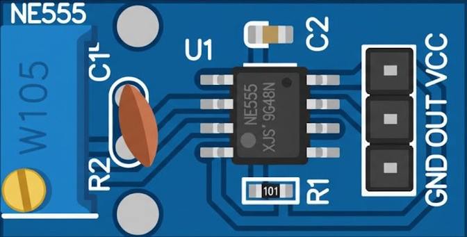
The NE555 Pulse Generator Module is a versatile and widely used electronic component based on the NE555 timer IC. It is designed to generate precise timing pulses and oscillations, making it an essential tool for a variety of applications. The module simplifies the use of the NE555 IC by integrating necessary components such as resistors, capacitors, and potentiometers, allowing users to easily adjust the output frequency and duty cycle.
Explore Projects Built with ne555 Pulse Generator Module


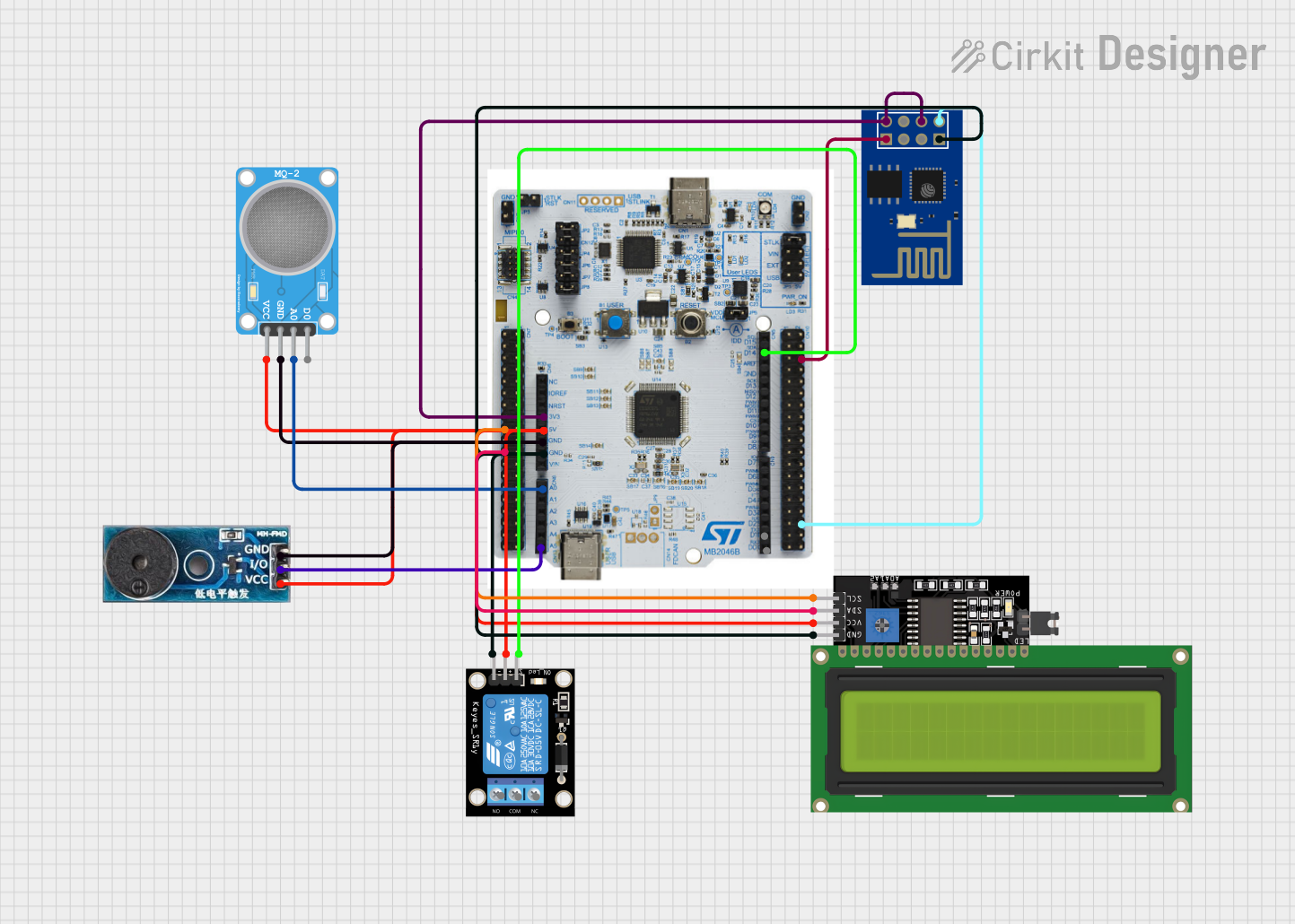
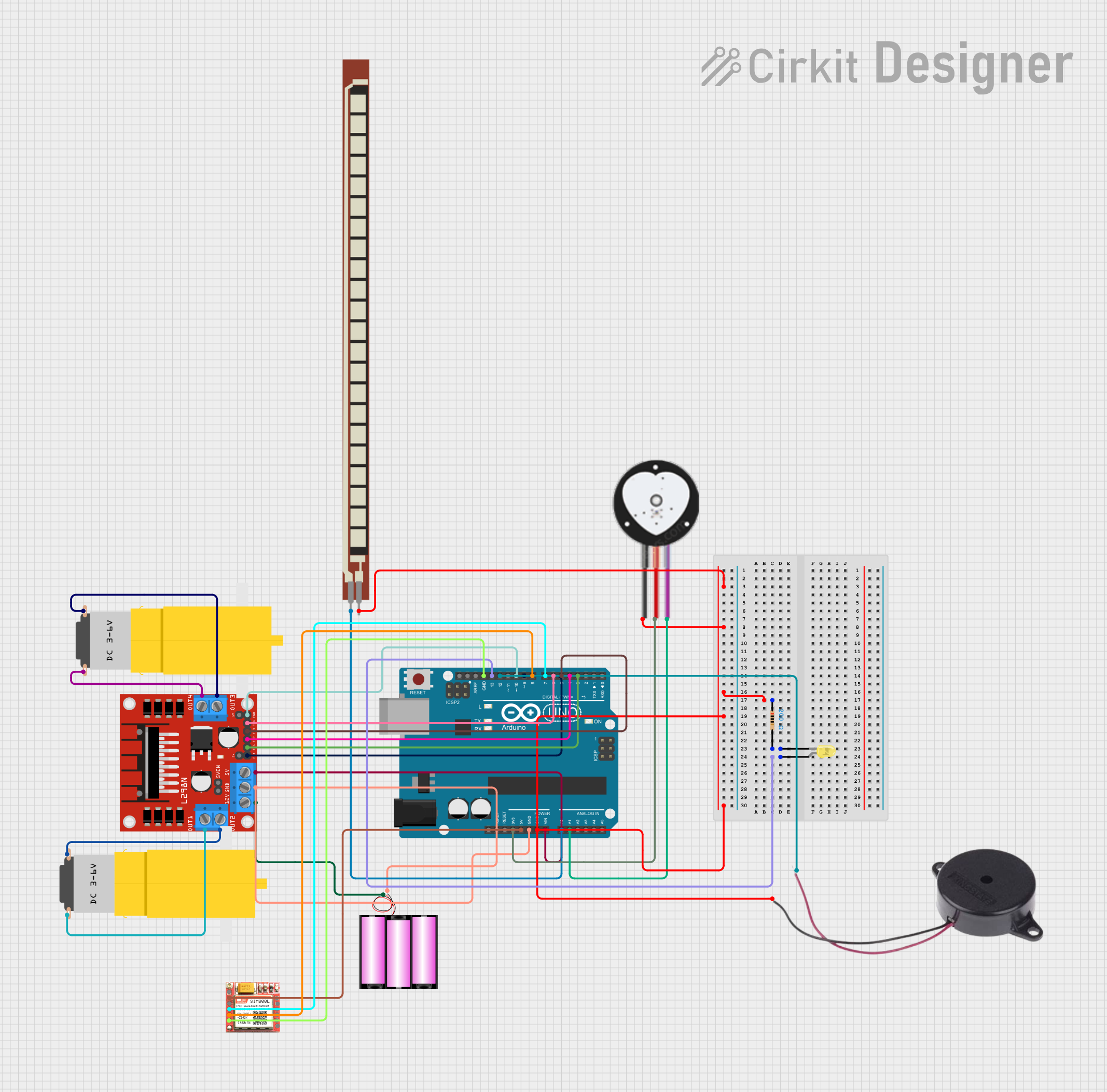
Explore Projects Built with ne555 Pulse Generator Module
Common Applications and Use Cases
- Timers: Used in delay circuits and time-based control systems.
- Pulse Width Modulation (PWM): For controlling motor speed, LED brightness, and more.
- Frequency Generation: Produces square wave signals for testing and signal processing.
- Oscillators: Generates clock signals for digital circuits.
- Tone Generation: Used in audio applications to produce sound waves.
Technical Specifications
The NE555 Pulse Generator Module is built around the NE555 timer IC and includes additional components for ease of use. Below are the key technical details:
General Specifications
- Operating Voltage: 5V to 15V DC
- Output Signal: Square wave
- Frequency Range: ~1Hz to 200kHz (adjustable via potentiometers)
- Duty Cycle: Adjustable (typically 10% to 90%)
- Output Current: Up to 200mA
- Output Voltage: Approximately equal to the input voltage
- Dimensions: Varies by manufacturer, typically compact (e.g., 3cm x 2cm)
Pin Configuration and Descriptions
The module typically has a 4-pin interface for easy integration into circuits. Below is the pinout:
| Pin | Name | Description |
|---|---|---|
| 1 | VCC | Power supply input (5V to 15V DC). |
| 2 | GND | Ground connection. |
| 3 | OUT | Output pin that provides the square wave signal. |
| 4 | ADJ (optional) | Adjustment pin for fine-tuning frequency and duty cycle (connected to potentiometer). |
Usage Instructions
The NE555 Pulse Generator Module is straightforward to use and can be integrated into various circuits. Follow the steps below to use the module effectively:
Basic Setup
- Power the Module: Connect the VCC pin to a DC power supply (5V to 15V) and the GND pin to the ground.
- Connect the Output: Use the OUT pin to connect the module to the desired load or circuit.
- Adjust Frequency and Duty Cycle: Use the onboard potentiometers to fine-tune the output frequency and duty cycle as needed.
Important Considerations
- Power Supply: Ensure the input voltage is within the specified range to avoid damaging the module.
- Load Compatibility: The output current is limited to 200mA. Use a transistor or MOSFET if higher current is required.
- Signal Stability: For precise applications, use a stable power supply to minimize noise and fluctuations.
Example: Using with Arduino UNO
The NE555 Pulse Generator Module can be used with an Arduino UNO to generate a square wave signal. Below is an example of how to read the output signal using the Arduino:
Circuit Connection
- Connect the module's VCC and GND to the Arduino's 5V and GND pins, respectively.
- Connect the OUT pin of the module to Arduino's digital pin 2.
Arduino Code
// Example code to read the NE555 Pulse Generator Module output
// and display the frequency on the Serial Monitor.

const int pulsePin = 2; // Pin connected to the module's OUT pin
unsigned long duration; // Variable to store pulse duration
float frequency;        // Variable to store calculated frequency

void setup() {
  pinMode(pulsePin, INPUT); // Set the pulse pin as input
  Serial.begin(9600);       // Initialize Serial communication
}

void loop() {
  // Measure the duration of a HIGH pulse
  duration = pulseIn(pulsePin, HIGH);

  // Calculate frequency (1 / period), where period = 2 * duration
  if (duration > 0) {
    frequency = 1.0 / (2 * duration * 1e-6); // Convert microseconds to seconds
    Serial.print("Frequency: ");
    Serial.print(frequency);
    Serial.println(" Hz");
  } else {
    Serial.println("No signal detected.");
  }

  delay(500); // Wait for 500ms before the next reading
}
Notes
- The
pulseIn()function measures the duration of a HIGH pulse in microseconds. - Ensure the module's output frequency is within the Arduino's measurable range (up to ~1MHz).
Troubleshooting and FAQs
Common Issues and Solutions
No Output Signal
- Cause: Incorrect power supply or loose connections.
- Solution: Verify the power supply voltage and ensure all connections are secure.
Unstable Frequency
- Cause: Noise or fluctuations in the power supply.
- Solution: Use a regulated power supply and add decoupling capacitors (e.g., 0.1µF) near the module.
Output Signal Not Detected by Arduino
- Cause: Frequency is too high or too low for the Arduino to measure.
- Solution: Adjust the module's frequency using the potentiometers to bring it within the Arduino's range.
Overheating
- Cause: Excessive current draw from the output pin.
- Solution: Use a transistor or MOSFET to drive high-current loads.
FAQs
Q: Can the module generate a sine wave?
A: No, the module generates a square wave. For sine waves, additional circuitry is required.Q: How do I adjust the duty cycle?
A: Use the onboard potentiometer labeled for duty cycle adjustment. Refer to the module's datasheet for precise control.Q: Can I use this module with a 3.3V system?
A: The module typically requires a minimum of 5V. Check the specific module's datasheet for compatibility with lower voltages.Q: What is the maximum frequency this module can generate?
A: The maximum frequency is approximately 200kHz, but this may vary slightly depending on the module's design.
By following this documentation, you can effectively use the NE555 Pulse Generator Module in your projects and troubleshoot common issues with ease.