Cirkit Designer Logo
Cirkit Designer
Your all-in-one circuit design IDE
Home / 
Component Documentation

How to Use ELRS/Crosfire Receiever Radiomaster RP1: Examples, Pinouts, and Specs

Image of ELRS/Crosfire Receiever Radiomaster RP1
Cirkit Designer LogoDesign with ELRS/Crosfire Receiever Radiomaster RP1 in Cirkit Designer

Introduction

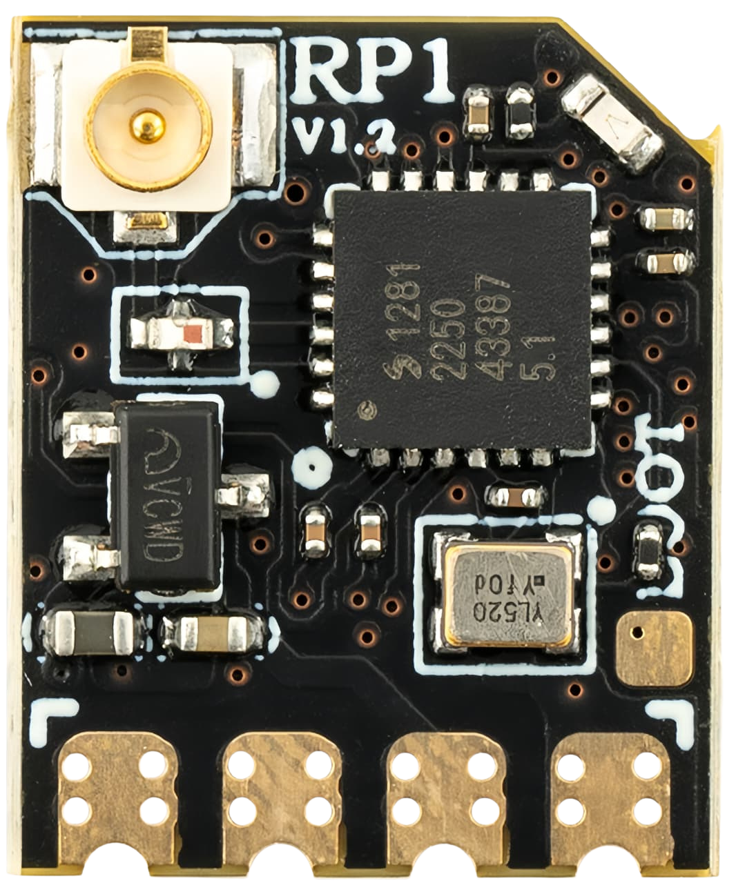
The Radiomaster RP1 is a high-performance receiver designed for long-range control in RC (Radio Control) applications. It is compatible with both ELRS (ExpressLRS) and Crossfire protocols, making it a versatile choice for hobbyists and professionals alike. The RP1 offers low latency, robust signal reliability, and excellent range, making it ideal for drones, RC planes, and other remote-controlled devices.

Explore Projects Built with ELRS/Crosfire Receiever Radiomaster RP1

Use Cirkit Designer to design, explore, and prototype these projects online. Some projects support real-time simulation. Click "Open Project" to start designing instantly!
Satellite-Based Timing and Navigation System with SDR and Atomic Clock Synchronization
Image of GPS 시스템 측정 구성도_Confirm: A project utilizing ELRS/Crosfire Receiever Radiomaster RP1 in a practical application
This circuit appears to be a complex system involving power supply management, GPS and timing synchronization, and data communication. It includes a SI-TEX G1 Satellite Compass for GPS data, an XHTF1021 Atomic Rubidium Clock for precise timing, and Ettus USRP B200 units for software-defined radio communication. Power is supplied through various SMPS units and distributed via terminal blocks and DC jacks. Data communication is facilitated by Beelink MINI S12 N95 computers, RS232 splitters, and a 1000BASE-T Media Converter for network connectivity. RF Directional Couplers are used to interface antennas with the USRP units, and the entire system is likely contained within cases for protection and organization.
Cirkit Designer LogoOpen Project in Cirkit Designer
Arduino Pro Mini FM Radio with LCD Display and Battery Power
Image of DIY FM Radio RDA5807M V2: A project utilizing ELRS/Crosfire Receiever Radiomaster RP1 in a practical application
This circuit is a portable FM radio receiver with an integrated display and audio output. It uses an Arduino Pro Mini to control an RDA5807M FM receiver module, an ADS1115 ADC for additional analog inputs, and a PAM8403 amplifier to drive loudspeakers. The circuit also includes a rotary encoder for user input, an LCD screen for displaying information, and a boost converter for power management.
Cirkit Designer LogoOpen Project in Cirkit Designer
ESP32-Based RF Communication System with 433 MHz Modules
Image of 433 mhz: A project utilizing ELRS/Crosfire Receiever Radiomaster RP1 in a practical application
This circuit comprises an ESP32 microcontroller connected to a 433 MHz RF transmitter and receiver pair. The ESP32 is programmed to receive and decode RF signals through the receiver module, as well as send RF signals via the transmitter module. Additionally, the ESP32 can communicate with a Bluetooth device to exchange commands and data, and it uses an LED for status indication.
Cirkit Designer LogoOpen Project in Cirkit Designer
Satellite Compass and Network-Integrated GPS Data Processing System
Image of GPS 시스템 측정 구성도_241016: A project utilizing ELRS/Crosfire Receiever Radiomaster RP1 in a practical application
This circuit comprises a satellite compass, a mini PC, two GPS antennas, power supplies, a network switch, media converters, and an atomic rubidium clock. The satellite compass is powered by a triple output DC power supply and interfaces with an RS232 splitter for 1PPS signals. The mini PCs are connected to the USRP B200 devices via USB for data and power, and to media converters via Ethernet, which in turn connect to a network switch using fiber optic links. The antennas are connected to the USRP B200s through RF directional couplers, and the atomic clock provides a 1PPS input to the RS232 splitter.
Cirkit Designer LogoOpen Project in Cirkit Designer

Explore Projects Built with ELRS/Crosfire Receiever Radiomaster RP1

Use Cirkit Designer to design, explore, and prototype these projects online. Some projects support real-time simulation. Click "Open Project" to start designing instantly!
Image of GPS 시스템 측정 구성도_Confirm: A project utilizing ELRS/Crosfire Receiever Radiomaster RP1 in a practical application
Satellite-Based Timing and Navigation System with SDR and Atomic Clock Synchronization
This circuit appears to be a complex system involving power supply management, GPS and timing synchronization, and data communication. It includes a SI-TEX G1 Satellite Compass for GPS data, an XHTF1021 Atomic Rubidium Clock for precise timing, and Ettus USRP B200 units for software-defined radio communication. Power is supplied through various SMPS units and distributed via terminal blocks and DC jacks. Data communication is facilitated by Beelink MINI S12 N95 computers, RS232 splitters, and a 1000BASE-T Media Converter for network connectivity. RF Directional Couplers are used to interface antennas with the USRP units, and the entire system is likely contained within cases for protection and organization.
Cirkit Designer LogoOpen Project in Cirkit Designer
Image of DIY FM Radio RDA5807M V2: A project utilizing ELRS/Crosfire Receiever Radiomaster RP1 in a practical application
Arduino Pro Mini FM Radio with LCD Display and Battery Power
This circuit is a portable FM radio receiver with an integrated display and audio output. It uses an Arduino Pro Mini to control an RDA5807M FM receiver module, an ADS1115 ADC for additional analog inputs, and a PAM8403 amplifier to drive loudspeakers. The circuit also includes a rotary encoder for user input, an LCD screen for displaying information, and a boost converter for power management.
Cirkit Designer LogoOpen Project in Cirkit Designer
Image of 433 mhz: A project utilizing ELRS/Crosfire Receiever Radiomaster RP1 in a practical application
ESP32-Based RF Communication System with 433 MHz Modules
This circuit comprises an ESP32 microcontroller connected to a 433 MHz RF transmitter and receiver pair. The ESP32 is programmed to receive and decode RF signals through the receiver module, as well as send RF signals via the transmitter module. Additionally, the ESP32 can communicate with a Bluetooth device to exchange commands and data, and it uses an LED for status indication.
Cirkit Designer LogoOpen Project in Cirkit Designer
Image of GPS 시스템 측정 구성도_241016: A project utilizing ELRS/Crosfire Receiever Radiomaster RP1 in a practical application
Satellite Compass and Network-Integrated GPS Data Processing System
This circuit comprises a satellite compass, a mini PC, two GPS antennas, power supplies, a network switch, media converters, and an atomic rubidium clock. The satellite compass is powered by a triple output DC power supply and interfaces with an RS232 splitter for 1PPS signals. The mini PCs are connected to the USRP B200 devices via USB for data and power, and to media converters via Ethernet, which in turn connect to a network switch using fiber optic links. The antennas are connected to the USRP B200s through RF directional couplers, and the atomic clock provides a 1PPS input to the RS232 splitter.
Cirkit Designer LogoOpen Project in Cirkit Designer

Common Applications and Use Cases

  • Long-range FPV (First Person View) drones
  • RC planes and helicopters
  • Remote-controlled cars and boats
  • Robotics and automation projects requiring reliable wireless communication

Technical Specifications

The Radiomaster RP1 is engineered to deliver exceptional performance in demanding environments. Below are its key technical specifications:

Specification Details
Protocol Compatibility ELRS (ExpressLRS) / Crossfire
Frequency Range 2.4 GHz
Input Voltage Range 5V
Antenna Type External, IPEX connector
Latency Ultra-low (as low as 4ms)
Range Up to 15 km (depending on setup)
Dimensions 10 mm x 15 mm x 3 mm
Weight 1.5 g
Firmware Update Method Over-the-Air (OTA) or USB

Pin Configuration and Descriptions

The Radiomaster RP1 features a simple pinout for easy integration into your projects. Below is the pin configuration:

Pin Label Description
1 GND Ground connection
2 5V Power input (5V)
3 TX UART Transmit (to flight controller RX)
4 RX UART Receive (to flight controller TX)

Usage Instructions

How to Use the Radiomaster RP1 in a Circuit

  1. Power Connection: Connect the 5V pin to a 5V power source and the GND pin to ground.
  2. UART Connection: Connect the TX pin of the RP1 to the RX pin of your flight controller, and the RX pin of the RP1 to the TX pin of your flight controller.
  3. Antenna Installation: Attach the included antenna to the IPEX connector. Ensure the antenna is securely connected to avoid signal loss.
  4. Binding: Follow the binding procedure for your chosen protocol (ELRS or Crossfire). For ELRS, use the ExpressLRS Configurator to set up the receiver and transmitter.

Important Considerations and Best Practices

  • Antenna Placement: Ensure the antenna is positioned away from metal components and other electronics to minimize interference.
  • Firmware Updates: Keep the firmware up to date using the Over-the-Air (OTA) method or USB to ensure optimal performance and compatibility.
  • Power Supply: Use a stable 5V power source to avoid damage to the receiver.
  • Protocol Selection: Ensure your transmitter is set to the same protocol (ELRS or Crossfire) as the receiver.

Example Code for Arduino UNO

If you are using the Radiomaster RP1 with an Arduino UNO for a custom RC project, you can use the following example code to establish communication:

#include <SoftwareSerial.h>

// Define RX and TX pins for the Arduino
#define RX_PIN 10  // Connect to RP1 TX pin
#define TX_PIN 11  // Connect to RP1 RX pin

// Initialize SoftwareSerial for communication with the RP1
SoftwareSerial RP1Serial(RX_PIN, TX_PIN);

void setup() {
  // Start serial communication with the RP1
  RP1Serial.begin(115200); // Set baud rate to match the RP1
  Serial.begin(9600);      // For debugging via Serial Monitor

  Serial.println("Radiomaster RP1 Receiver Initialized");
}

void loop() {
  // Check if data is available from the RP1
  if (RP1Serial.available()) {
    String receivedData = RP1Serial.readString();
    Serial.print("Data from RP1: ");
    Serial.println(receivedData);
  }

  // Example: Send data to the RP1
  RP1Serial.println("Hello RP1");
  delay(1000); // Wait 1 second before sending again
}

Notes:

  • Ensure the baud rate in the code matches the configuration of the RP1.
  • Use appropriate level shifters if your Arduino operates at 5V logic levels, as the RP1 may use 3.3V logic.

Troubleshooting and FAQs

Common Issues and Solutions

  1. Receiver Not Binding to Transmitter

    • Ensure both the receiver and transmitter are set to the same protocol (ELRS or Crossfire).
    • Check that the firmware versions of the receiver and transmitter are compatible.
    • Follow the binding procedure carefully, ensuring the receiver is in binding mode.
  2. Poor Signal Range

    • Verify that the antenna is securely connected and properly positioned.
    • Avoid placing the receiver near sources of interference, such as motors or ESCs.
    • Check for damage to the antenna or receiver.
  3. No Communication with Flight Controller

    • Double-check the UART connections (TX to RX and RX to TX).
    • Ensure the correct UART port is enabled in your flight controller's configuration software (e.g., Betaflight).
  4. Firmware Update Fails

    • Ensure the receiver is powered correctly during the update process.
    • Use a stable USB connection or reliable OTA method.
    • Verify that the firmware file is correct for the RP1.

FAQs

Q: Can I use the RP1 with a 3.3V power source?
A: No, the RP1 requires a 5V power source for proper operation.

Q: How do I switch between ELRS and Crossfire protocols?
A: The protocol is determined by the firmware loaded onto the receiver. Use the appropriate firmware for your desired protocol.

Q: What is the maximum range of the RP1?
A: The RP1 can achieve a range of up to 15 km, depending on environmental conditions and antenna placement.

Q: Can I use the RP1 with other transmitters besides Radiomaster?
A: Yes, as long as the transmitter supports ELRS or Crossfire protocols, it will be compatible with the RP1.