
How to Use Nokia 6100 Color LCD: Examples, Pinouts, and Specs

 Design with Nokia 6100 Color LCD in Cirkit Designer
Introduction
The Nokia 6100 Color LCD is a compact, full-color liquid crystal display originally used in the Nokia 6100 mobile phone. It features a resolution of 128x128 pixels and is capable of displaying vibrant graphics and text. This display is popular among hobbyists and developers for its affordability, small size, and ability to render colorful visuals in embedded systems.
Explore Projects Built with Nokia 6100 Color LCD
 Open Project in Cirkit Designer
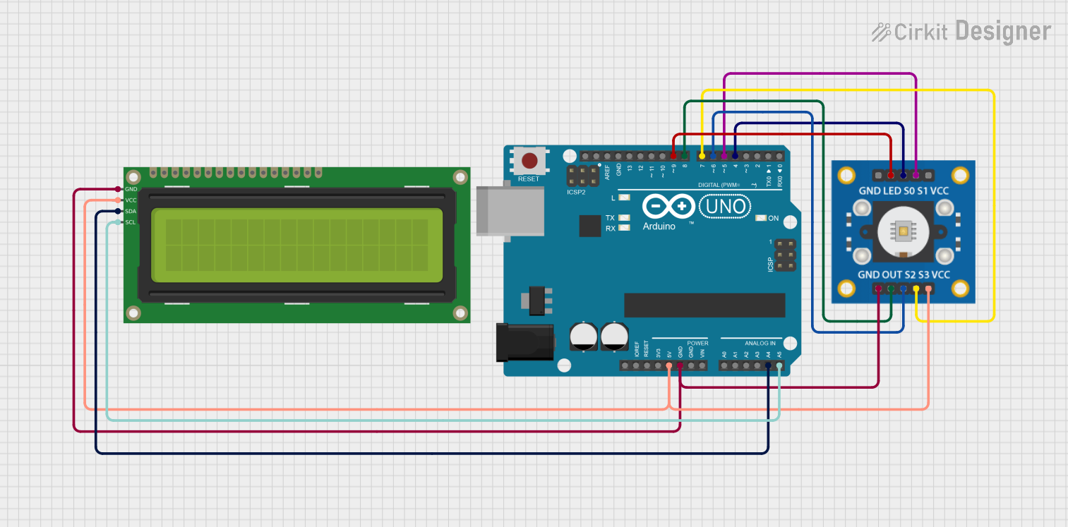 Open Project in Cirkit Designer
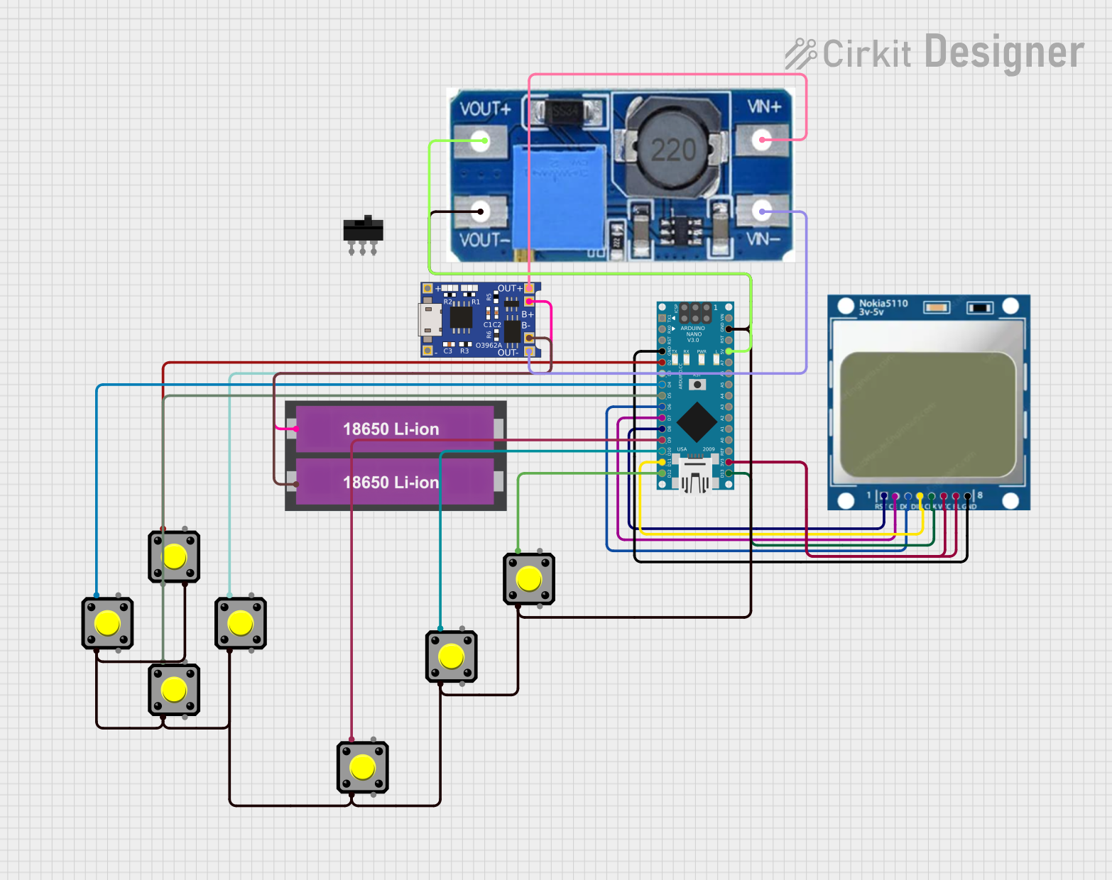 Open Project in Cirkit Designer
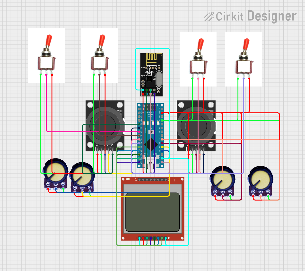 Open Project in Cirkit Designer
Explore Projects Built with Nokia 6100 Color LCD
Open Project in Cirkit DesignerOpen Project in Cirkit DesignerOpen Project in Cirkit DesignerOpen Project in Cirkit DesignerCommon Applications and Use Cases
- DIY electronics projects
- Embedded systems requiring graphical displays
- Portable devices and wearables
- Educational projects for learning about LCD interfacing
- Arduino and microcontroller-based projects
Technical Specifications
Below are the key technical details of the Nokia 6100 Color LCD:
| Specification | Details |
|---|---|
| Display Type | TFT LCD |
| Resolution | 128x128 pixels |
| Color Depth | 12-bit or 16-bit (4096/65,536 colors) |
| Interface | Serial Peripheral Interface (SPI) |
| Operating Voltage | 2.8V to 3.3V |
| Backlight | White LED |
| Dimensions | 35mm x 35mm x 2mm |
| Controller IC | Philips PCF8833 or Epson S1D15G10 |
Pin Configuration and Descriptions
The Nokia 6100 LCD typically comes with an 8-pin interface. Below is the pinout and description:
| Pin | Name | Description |
|---|---|---|
| 1 | GND | Ground connection |
| 2 | VCC | Power supply (2.8V to 3.3V) |
| 3 | SCLK | Serial clock input for SPI communication |
| 4 | SDATA | Serial data input for SPI communication |
| 5 | CS | Chip select (active low) |
| 6 | RESET | Reset signal (active low) |
| 7 | LED+ | Backlight positive terminal (connect to 3.3V via resistor) |
| 8 | LED- | Backlight negative terminal (connect to GND) |
Usage Instructions
How to Use the Nokia 6100 LCD in a Circuit
- Power Supply: Ensure the LCD is powered with a voltage between 2.8V and 3.3V. Use a voltage regulator if your system operates at 5V.
- SPI Communication: Connect the SCLK, SDATA, and CS pins to the corresponding SPI pins on your microcontroller.
- Backlight: Connect the LED+ pin to 3.3V through a current-limiting resistor (typically 100Ω) and the LED- pin to GND.
- Reset: Connect the RESET pin to a GPIO pin on your microcontroller for initialization.
- Initialization: Use the appropriate initialization sequence for the controller IC (PCF8833 or S1D15G10).
Important Considerations and Best Practices
- Voltage Levels: The LCD operates at 3.3V logic levels. If using a 5V microcontroller (e.g., Arduino UNO), use level shifters or voltage dividers to avoid damaging the display.
- Backlight Current: Do not exceed the recommended current for the backlight LED to prevent overheating.
- Controller IC: Verify the controller IC (PCF8833 or S1D15G10) and use the correct initialization commands for proper operation.
- SPI Speed: Use an appropriate SPI clock speed (typically up to 4 MHz) to ensure reliable communication.
Example Code for Arduino UNO
Below is an example of interfacing the Nokia 6100 LCD with an Arduino UNO using the Adafruit GFX library:
#include <Adafruit_GFX.h>       // Graphics library for drawing shapes and text
#include <Adafruit_PCD8544.h>   // Library for Nokia LCD (modify for PCF8833/S1D15G10)

// Pin definitions for SPI communication
#define SCLK 13  // Serial clock pin
#define SDATA 11 // Serial data pin
#define CS    10 // Chip select pin
#define RESET 9  // Reset pin

// Initialize the display (modify for PCF8833/S1D15G10)
Adafruit_PCD8544 display(SCLK, SDATA, CS, RESET);

void setup() {
  // Initialize the display
  display.begin();
  display.setContrast(50); // Adjust contrast as needed

  // Clear the display
  display.clearDisplay();

  // Draw a simple message
  display.setTextSize(1);       // Set text size
  display.setTextColor(BLACK);  // Set text color
  display.setCursor(0, 0);      // Set cursor position
  display.println("Hello, World!");
  display.display();            // Update the display
}

void loop() {
  // Add any additional functionality here
}
Notes:
- Replace the
Adafruit_PCD8544library with a library compatible with the PCF8833 or S1D15G10 controller. - Adjust the initialization sequence and commands based on the specific controller IC.
Troubleshooting and FAQs
Common Issues and Solutions
No Display Output:
- Verify all connections, especially power and SPI pins.
- Ensure the LCD is receiving the correct voltage (2.8V to 3.3V).
- Check the initialization sequence for the correct controller IC.
Flickering or Distorted Graphics:
- Reduce the SPI clock speed to improve communication reliability.
- Ensure proper grounding and minimize noise in the circuit.
Backlight Not Working:
- Check the current-limiting resistor value for the backlight LED.
- Verify the LED+ and LED- connections.
Incorrect Colors or Resolution:
- Confirm the color depth (12-bit or 16-bit) and resolution settings in your code.
- Ensure the correct library and commands are used for the controller IC.
FAQs
Q: Can I use the Nokia 6100 LCD with a 5V microcontroller?
A: Yes, but you must use level shifters or voltage dividers to convert 5V logic to 3.3V logic.
Q: How do I identify the controller IC on my LCD?
A: Check the product documentation or inspect the LCD module for markings indicating the controller type (PCF8833 or S1D15G10).
Q: What is the maximum SPI clock speed for this LCD?
A: The typical maximum SPI clock speed is 4 MHz, but this may vary depending on the controller IC and wiring quality.
Q: Can I use this LCD for video playback?
A: While possible, the low resolution (128x128) and limited refresh rate make it unsuitable for smooth video playback.
By following this documentation, you can successfully integrate the Nokia 6100 Color LCD into your projects and troubleshoot common issues effectively.