How to Use A7670c: Examples, Pinouts, and Specs
Introduction
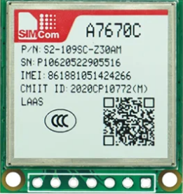
The A7670c is a compact, low-power, high-performance RF transceiver designed for wireless communication applications. Operating in the 2.4 GHz ISM band, it supports various modulation schemes, including GFSK, O-QPSK, and DSSS, making it ideal for Internet of Things (IoT) devices, short-range wireless networks, and industrial automation systems. Its small form factor and energy efficiency make it a popular choice for battery-powered devices.
Explore Projects Built with A7670c


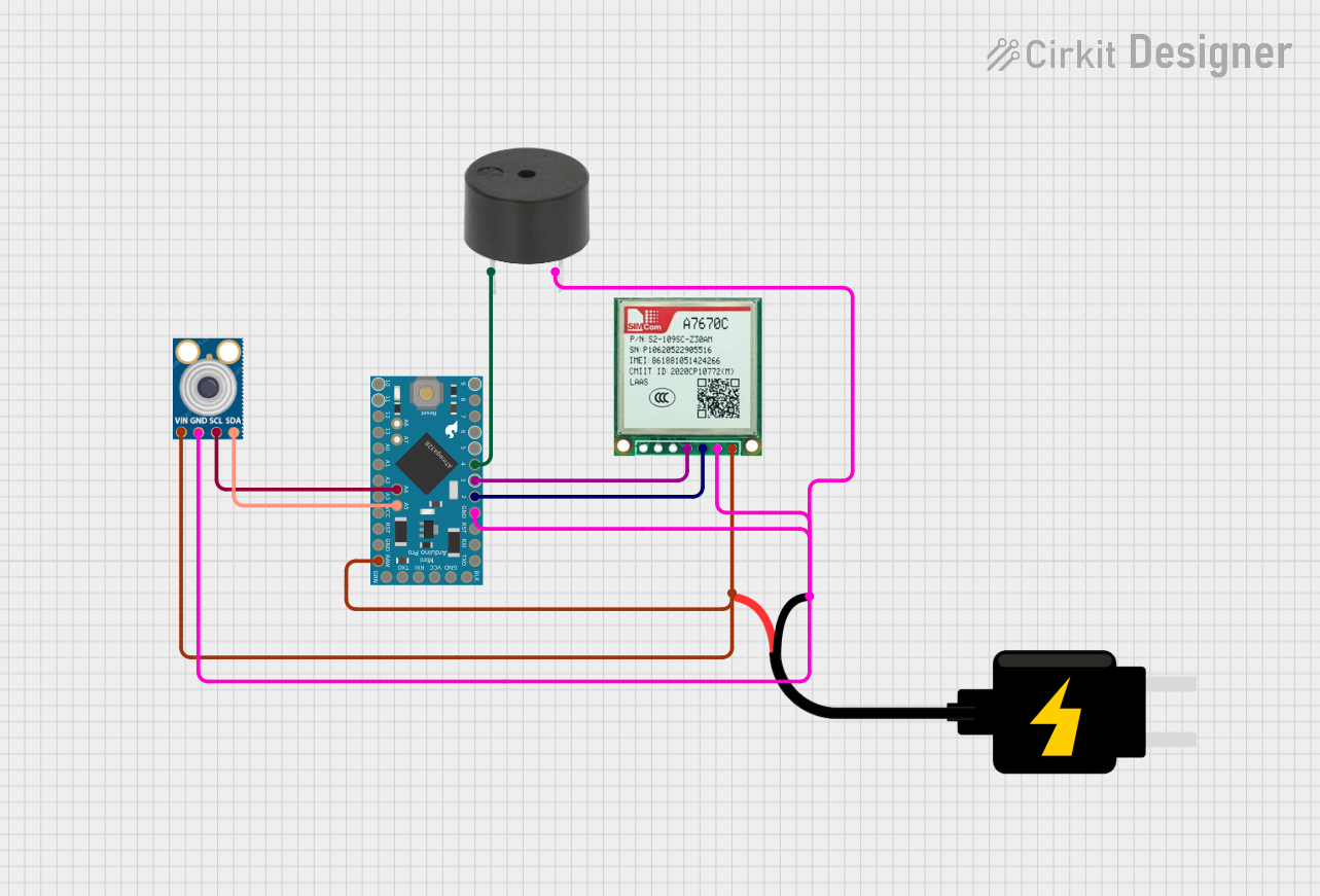
Explore Projects Built with A7670c
Common Applications
- IoT devices (e.g., smart home sensors, wearables)
- Short-range wireless communication networks
- Industrial automation and control systems
- Wireless data transmission in medical devices
- Consumer electronics (e.g., wireless keyboards, mice)
Technical Specifications
The A7670c is designed to deliver reliable performance in a wide range of wireless communication scenarios. Below are its key technical specifications:
| Parameter | Value |
|---|---|
| Operating Frequency | 2.4 GHz ISM Band |
| Modulation Schemes | GFSK, O-QPSK, DSSS |
| Data Rate | Up to 2 Mbps |
| Supply Voltage | 1.8V to 3.6V |
| Current Consumption | 15 mA (TX mode), 12 mA (RX mode) |
| Sleep Mode Current | < 1 µA |
| Operating Temperature | -40°C to +85°C |
| Communication Interface | SPI |
| Output Power | Up to +4 dBm |
| Sensitivity | -95 dBm at 1 Mbps |
| Package Type | QFN-24 |
Pin Configuration and Descriptions
The A7670c comes in a 24-pin QFN package. Below is the pin configuration and description:
| Pin Number | Pin Name | Description |
|---|---|---|
| 1 | VDD | Power supply input (1.8V to 3.6V) |
| 2 | GND | Ground |
| 3 | SCK | SPI clock input |
| 4 | MOSI | SPI data input (Master Out, Slave In) |
| 5 | MISO | SPI data output (Master In, Slave Out) |
| 6 | CSN | Chip select (active low) |
| 7 | IRQ | Interrupt request output |
| 8 | TX_EN | Transmit enable |
| 9 | RX_EN | Receive enable |
| 10 | ANT | Antenna connection |
| 11-24 | NC | Not connected (reserved for future use) |
Usage Instructions
How to Use the A7670c in a Circuit
- Power Supply: Connect the VDD pin to a stable power source (1.8V to 3.6V) and the GND pin to ground.
- SPI Communication: Interface the A7670c with a microcontroller using the SPI pins (SCK, MOSI, MISO, and CSN). Ensure the SPI clock frequency is within the supported range.
- Antenna Connection: Attach a suitable 2.4 GHz antenna to the ANT pin for optimal wireless performance.
- Mode Selection: Use the TX_EN and RX_EN pins to toggle between transmit and receive modes.
- Interrupt Handling: Connect the IRQ pin to the microcontroller to handle events such as data reception or transmission completion.
Important Considerations
- Use decoupling capacitors (e.g., 0.1 µF) near the VDD pin to reduce noise and ensure stable operation.
- Keep the antenna trace as short as possible and use impedance matching techniques for better RF performance.
- Avoid placing the A7670c near high-frequency components or metal enclosures to minimize interference.
- Ensure proper grounding to reduce noise and improve signal integrity.
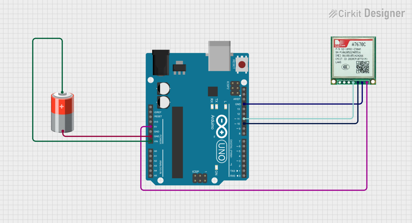
Example: Connecting the A7670c to an Arduino UNO
Below is an example of how to connect the A7670c to an Arduino UNO and send data wirelessly:
Wiring Diagram
| A7670c Pin | Arduino UNO Pin |
|---|---|
| VDD | 3.3V |
| GND | GND |
| SCK | D13 |
| MOSI | D11 |
| MISO | D12 |
| CSN | D10 |
| IRQ | D2 |
Arduino Code Example
#include <SPI.h>

// Define A7670c pins
#define CSN_PIN 10  // Chip select pin
#define IRQ_PIN 2   // Interrupt pin

void setup() {
  // Initialize SPI communication
  SPI.begin();
  pinMode(CSN_PIN, OUTPUT);
  pinMode(IRQ_PIN, INPUT);

  // Set CSN high to deselect the A7670c
  digitalWrite(CSN_PIN, HIGH);

  // Initialize serial communication for debugging
  Serial.begin(9600);
  Serial.println("A7670c Initialization...");

  // Example: Configure the A7670c (pseudo-configuration)
  configureA7670c();
}

void loop() {
  // Example: Send data wirelessly
  sendData("Hello, A7670c!");
  delay(1000);  // Wait 1 second before sending again
}

void configureA7670c() {
  // Example configuration function
  digitalWrite(CSN_PIN, LOW);  // Select the A7670c
  SPI.transfer(0x01);          // Send a configuration command
  SPI.transfer(0x00);          // Example data
  digitalWrite(CSN_PIN, HIGH); // Deselect the A7670c
  Serial.println("A7670c Configured.");
}

void sendData(const char* data) {
  // Example function to send data
  digitalWrite(CSN_PIN, LOW);  // Select the A7670c
  SPI.transfer(0x02);          // Send a transmit command
  while (*data) {
    SPI.transfer(*data++);     // Send each character
  }
  digitalWrite(CSN_PIN, HIGH); // Deselect the A7670c
  Serial.println("Data Sent.");
}
Troubleshooting and FAQs
Common Issues and Solutions
No Communication with the A7670c
- Solution: Verify the SPI connections and ensure the CSN pin is correctly toggled.
- Tip: Check the SPI clock frequency and ensure it matches the A7670c's requirements.
Poor Wireless Range
- Solution: Ensure the antenna is properly connected and positioned. Avoid obstructions and interference from other devices.
- Tip: Use an external antenna with better gain if needed.
High Current Consumption
- Solution: Verify that the A7670c enters sleep mode when not in use. Check for any floating input pins.
- Tip: Use pull-up or pull-down resistors on unused pins to prevent floating states.
Data Transmission Errors
- Solution: Check the modulation scheme and data rate settings. Ensure both transmitter and receiver are configured identically.
- Tip: Use error-checking mechanisms like CRC to detect and correct transmission errors.
FAQs
Q: Can the A7670c operate at 5V?
A: No, the A7670c operates within a supply voltage range of 1.8V to 3.6V. Use a voltage regulator if your system operates at 5V.Q: What is the maximum data rate supported?
A: The A7670c supports data rates of up to 2 Mbps.Q: Is the A7670c compatible with Zigbee?
A: Yes, the A7670c supports modulation schemes like O-QPSK and DSSS, which are used in Zigbee communication.Q: How do I improve signal strength?
A: Use a high-gain antenna, minimize interference, and ensure proper grounding and impedance matching.
This concludes the documentation for the A7670c RF transceiver.