
How to Use 4001 4 x 2 Input NOR Gate: Examples, Pinouts, and Specs
 Design with 4001 4 x 2 Input NOR Gate in Cirkit Designer
Introduction
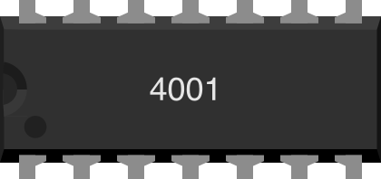
The 4001 IC is a digital logic gate integrated circuit (IC) that contains four independent 2-input NOR gates. A NOR gate is a fundamental building block in digital electronics, performing a logical operation that outputs true (logic HIGH) only when all its inputs are false (logic LOW). If any input is true, the output will be false.
The 4001 IC is widely used in digital circuits due to its simplicity and versatility. It is commonly employed in applications such as logic design, signal processing, and control systems. Its low power consumption and compatibility with CMOS technology make it suitable for a variety of projects.
Explore Projects Built with 4001 4 x 2 Input NOR Gate
 Open Project in Cirkit Designer
 Open Project in Cirkit Designer
 Open Project in Cirkit Designer
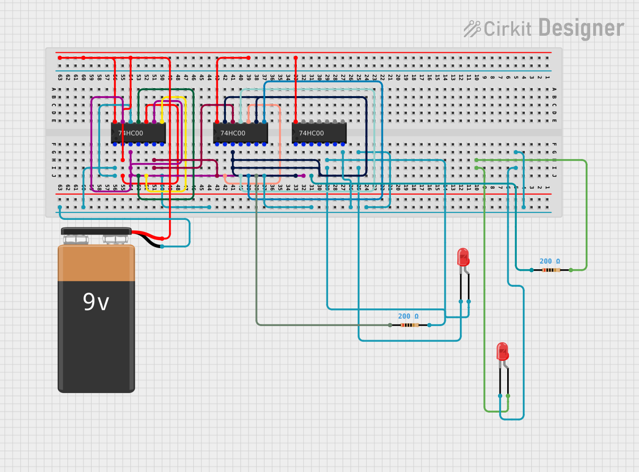 Open Project in Cirkit Designer
Explore Projects Built with 4001 4 x 2 Input NOR Gate
Open Project in Cirkit DesignerOpen Project in Cirkit DesignerOpen Project in Cirkit DesignerOpen Project in Cirkit DesignerTechnical Specifications
- Logic Family: CMOS
- Supply Voltage (Vcc): 3V to 15V
- Input Voltage Range: 0V to Vcc
- Output Voltage (HIGH): Close to Vcc
- Output Voltage (LOW): Close to 0V
- Propagation Delay: ~60 ns at Vcc = 5V
- Power Dissipation: ~10 µW at Vcc = 5V
- Operating Temperature Range: -55°C to +125°C
- Package Types: DIP-14, SOIC-14, and others
Pin Configuration and Descriptions
The 4001 IC is typically available in a 14-pin Dual Inline Package (DIP). Below is the pinout and description:
| Pin Number | Pin Name | Description |
|---|---|---|
| 1 | A1 | Input A for NOR Gate 1 |
| 2 | B1 | Input B for NOR Gate 1 |
| 3 | Q1 | Output of NOR Gate 1 |
| 4 | A2 | Input A for NOR Gate 2 |
| 5 | B2 | Input B for NOR Gate 2 |
| 6 | Q2 | Output of NOR Gate 2 |
| 7 | GND | Ground (0V) |
| 8 | Q3 | Output of NOR Gate 3 |
| 9 | A3 | Input A for NOR Gate 3 |
| 10 | B3 | Input B for NOR Gate 3 |
| 11 | Q4 | Output of NOR Gate 4 |
| 12 | A4 | Input A for NOR Gate 4 |
| 13 | B4 | Input B for NOR Gate 4 |
| 14 | Vcc | Positive Supply Voltage |
Usage Instructions
How to Use the 4001 IC in a Circuit
- Power Supply: Connect the Vcc pin (Pin 14) to a positive voltage source (3V to 15V) and the GND pin (Pin 7) to ground.
- Inputs: Provide logic signals (HIGH or LOW) to the input pins (A1, B1, A2, B2, etc.) of the desired NOR gate.
- Outputs: The output pins (Q1, Q2, Q3, Q4) will provide the NOR operation result based on the inputs.
- Pull-Down Resistors: If inputs are left floating, use pull-down resistors to ensure stable LOW signals.
Example Circuit
To demonstrate the functionality of a single NOR gate:
- Connect Pin 1 (A1) and Pin 2 (B1) to switches or logic inputs.
- Connect Pin 3 (Q1) to an LED with a current-limiting resistor.
- Observe the LED behavior:
- LED turns ON (logic HIGH) only when both inputs (A1 and B1) are LOW.
- LED turns OFF (logic LOW) if either or both inputs are HIGH.
Arduino Example Code
The 4001 IC can be interfaced with an Arduino UNO to demonstrate its functionality. Below is an example code:
// Define input pins for the NOR gate
const int inputA = 2; // Connect to A1 (Pin 1 of 4001)
const int inputB = 3; // Connect to B1 (Pin 2 of 4001)

// Define output pin for the NOR gate
const int outputQ = 4; // Connect to Q1 (Pin 3 of 4001)

void setup() {
  // Set input pins as outputs to simulate logic signals
  pinMode(inputA, OUTPUT);
  pinMode(inputB, OUTPUT);

  // Set output pin as input to read the NOR gate output
  pinMode(outputQ, INPUT);

  // Initialize inputs to LOW
  digitalWrite(inputA, LOW);
  digitalWrite(inputB, LOW);

  Serial.begin(9600); // Start serial communication for debugging
}

void loop() {
  // Test all input combinations
  for (int a = 0; a <= 1; a++) {
    for (int b = 0; b <= 1; b++) {
      digitalWrite(inputA, a); // Set input A
      digitalWrite(inputB, b); // Set input B

      delay(100); // Allow time for the NOR gate to process

      int output = digitalRead(outputQ); // Read the NOR gate output

      // Print the input and output states to the Serial Monitor
      Serial.print("Input A: ");
      Serial.print(a);
      Serial.print(", Input B: ");
      Serial.print(b);
      Serial.print(" -> Output Q: ");
      Serial.println(output);

      delay(500); // Wait before the next test
    }
  }
}
Important Considerations
- Ensure the supply voltage (Vcc) does not exceed the maximum rating of 15V.
- Avoid leaving input pins floating, as this can cause unpredictable behavior.
- Use decoupling capacitors (e.g., 0.1 µF) across the Vcc and GND pins to reduce noise.
Troubleshooting and FAQs
Common Issues
No Output Signal:
- Check the power supply connections (Vcc and GND).
- Verify that the input signals are within the acceptable voltage range.
Unstable Output:
- Ensure that unused inputs are tied to GND or Vcc using pull-down or pull-up resistors.
- Add decoupling capacitors to stabilize the power supply.
Incorrect Logic Behavior:
- Double-check the wiring of inputs and outputs.
- Confirm that the input logic levels match the expected HIGH and LOW voltages.
FAQs
Q1: Can the 4001 IC be used with a 5V power supply?
A1: Yes, the 4001 IC operates reliably with a supply voltage of 5V.
Q2: What happens if one input is left floating?
A2: Floating inputs can cause unpredictable behavior. Always tie unused inputs to GND or Vcc.
Q3: Can I use all four NOR gates simultaneously?
A3: Yes, all four NOR gates in the 4001 IC are independent and can be used simultaneously.
Q4: Is the 4001 IC compatible with TTL logic levels?
A4: The 4001 IC is a CMOS device and may not directly interface with TTL levels without level shifting. Ensure compatibility when designing mixed-logic circuits.