How to Use 30A Current Sensor: Examples, Pinouts, and Specs
Introduction
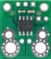
The ACS724 is a high-precision current sensor manufactured by Allegro Microsystems. It is designed to measure current in a circuit, with a maximum current handling capacity of 30 amperes. The sensor outputs an analog voltage signal proportional to the current flowing through it, making it ideal for interfacing with microcontrollers, such as Arduino, for real-time current monitoring.
Explore Projects Built with 30A Current Sensor


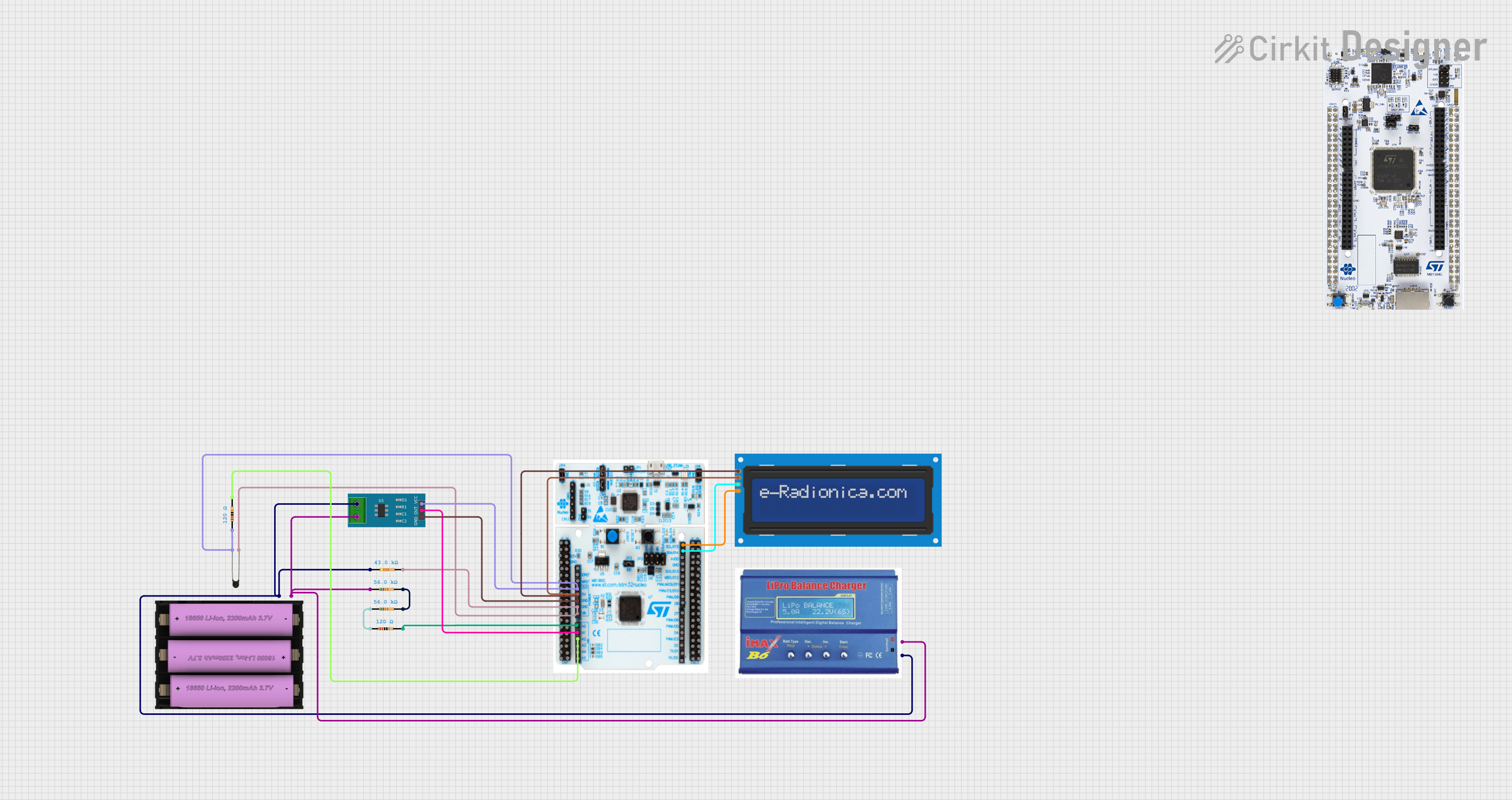
Explore Projects Built with 30A Current Sensor
Common Applications and Use Cases
- Battery management systems
- Motor control and monitoring
- Power supply monitoring
- Overcurrent protection in industrial systems
- Energy metering and load monitoring
Technical Specifications
The ACS724 is a Hall-effect-based current sensor with the following key specifications:
| Parameter | Value |
|---|---|
| Supply Voltage (Vcc) | 4.5V to 5.5V |
| Current Measurement Range | ±30A |
| Sensitivity | 40mV/A (typical) |
| Output Voltage Range | 0.5V to 4.5V |
| Zero Current Output Voltage | ~2.5V |
| Bandwidth | 120 kHz |
| Operating Temperature Range | -40°C to 150°C |
| Package Type | SOIC-8 |
Pin Configuration and Descriptions
The ACS724 comes in an 8-pin SOIC package. Below is the pinout and description:
| Pin Number | Pin Name | Description |
|---|---|---|
| 1 | IP+ | Positive current input terminal |
| 2 | IP- | Negative current input terminal |
| 3 | VIOUT | Analog voltage output proportional to current |
| 4 | GND | Ground connection |
| 5 | NC | No connection (leave unconnected) |
| 6 | NC | No connection (leave unconnected) |
| 7 | VCC | Supply voltage (4.5V to 5.5V) |
| 8 | FILTER | Optional external capacitor for noise filtering |
Usage Instructions
How to Use the ACS724 in a Circuit
- Power the Sensor: Connect the
VCCpin to a 5V power supply and theGNDpin to ground. - Current Path: Pass the current to be measured through the
IP+andIP-terminals. Ensure the current does not exceed the ±30A rating. - Output Signal: Connect the
VIOUTpin to an analog input pin of a microcontroller (e.g., Arduino) to read the voltage proportional to the current. - Filtering (Optional): For improved noise performance, connect a capacitor (e.g., 1nF to 10nF) between the
FILTERpin and ground.
Important Considerations and Best Practices
- Current Direction: The sensor outputs a voltage above 2.5V for positive current and below 2.5V for negative current.
- Calibration: For accurate measurements, calibrate the sensor by measuring the output voltage at zero current and adjusting your calculations accordingly.
- Thermal Management: Ensure proper heat dissipation if measuring high currents for extended periods.
- Noise Filtering: Use a capacitor on the
FILTERpin to reduce noise in the output signal.
Example Code for Arduino UNO
The following code demonstrates how to interface the ACS724 with an Arduino UNO to measure current:
// Define the analog pin connected to the ACS724 VIOUT pin
const int currentSensorPin = A0;

// Define the sensitivity of the ACS724 (40mV/A for ±30A version)
const float sensitivity = 0.04; // Sensitivity in V/A

// Define the zero-current output voltage (2.5V for ACS724)
const float zeroCurrentVoltage = 2.5; // Zero current voltage in volts

void setup() {
  Serial.begin(9600); // Initialize serial communication
}

void loop() {
  // Read the analog value from the sensor
  int sensorValue = analogRead(currentSensorPin);

  // Convert the analog value to voltage (5V reference, 10-bit ADC)
  float sensorVoltage = sensorValue * (5.0 / 1023.0);

  // Calculate the current in amperes
  float current = (sensorVoltage - zeroCurrentVoltage) / sensitivity;

  // Print the current to the Serial Monitor
  Serial.print("Current: ");
  Serial.print(current);
  Serial.println(" A");

  delay(500); // Wait for 500ms before the next reading
}
Troubleshooting and FAQs
Common Issues and Solutions
No Output Signal:
- Ensure the sensor is powered correctly (VCC = 5V, GND connected).
- Verify that the current path is properly connected to
IP+andIP-.
Inaccurate Readings:
- Check for proper calibration of the zero-current output voltage.
- Use a filtering capacitor on the
FILTERpin to reduce noise.
Output Voltage Stuck at 2.5V:
- Confirm that current is flowing through the sensor.
- Verify that the current does not exceed the ±30A range.
Overheating:
- Ensure the current does not exceed the sensor's maximum rating.
- Improve heat dissipation by using a heatsink or proper ventilation.
FAQs
Q: Can the ACS724 measure both AC and DC currents?
A: Yes, the ACS724 can measure both AC and DC currents, as it outputs a voltage proportional to the instantaneous current.
Q: What happens if the current exceeds 30A?
A: The sensor may become damaged or provide inaccurate readings. Always ensure the current stays within the specified range.
Q: Can I use the ACS724 with a 3.3V microcontroller?
A: The ACS724 requires a 5V supply, but its output can be read by a 3.3V microcontroller if the output voltage does not exceed the ADC input range. Use a voltage divider if necessary.
Q: How do I improve measurement accuracy?
A: Use a high-resolution ADC, calibrate the sensor, and add a filtering capacitor to reduce noise.