How to Use COPPER COIL - 25 TURNS: Examples, Pinouts, and Specs
Introduction
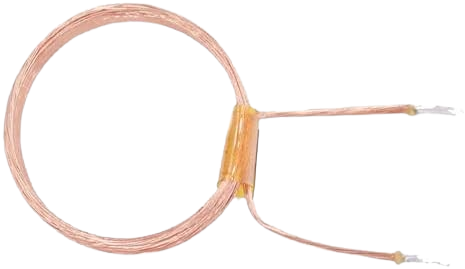
The Copper Coil - 25 Turns is a simple yet essential electronic component designed to generate a magnetic field when an electric current flows through it. This coil consists of 25 tightly wound turns of copper wire, making it ideal for applications requiring inductance or electromagnetic field generation. It is commonly used in inductors, transformers, electromagnets, and wireless charging systems.
Explore Projects Built with COPPER COIL - 25 TURNS

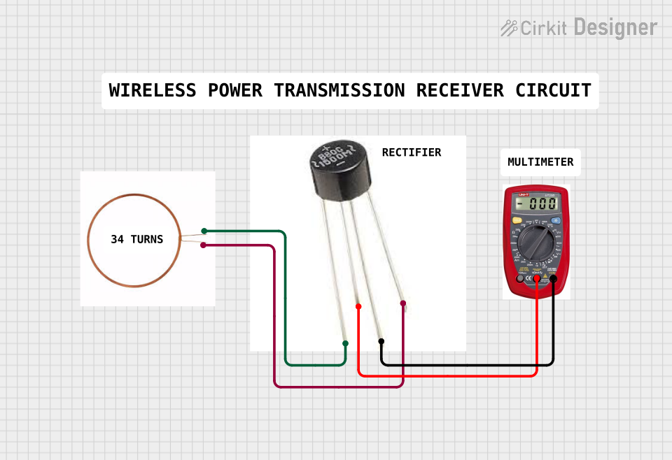

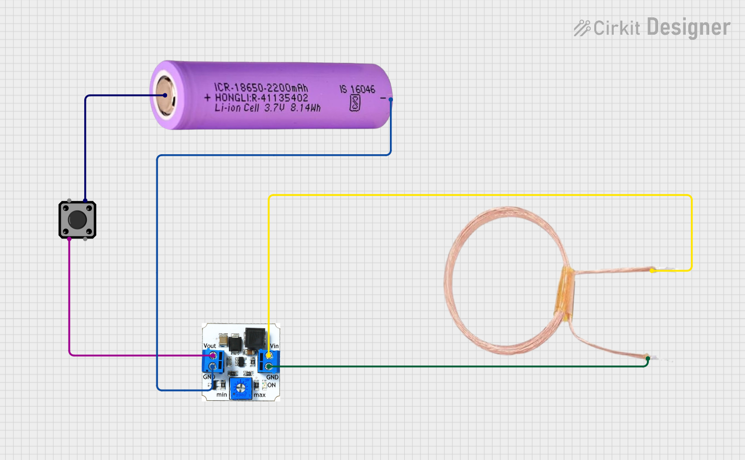
Explore Projects Built with COPPER COIL - 25 TURNS
Common Applications:
- Inductors in electronic circuits
- Transformers for voltage conversion
- Electromagnets for mechanical actuation
- Wireless power transfer systems
- RF (Radio Frequency) circuits and antennas
Technical Specifications
Key Technical Details:
| Parameter | Specification |
|---|---|
| Material | Copper |
| Number of Turns | 25 |
| Wire Gauge | 22 AWG (typical, may vary) |
| Inductance (approx.) | 10 µH to 50 µH (depends on core) |
| Resistance (DC) | ~0.1 Ω (varies with wire length) |
| Maximum Current | 2 A (depends on wire gauge) |
| Core Type | Air core (or optional ferrite) |
Pin Configuration and Description:
The copper coil does not have traditional "pins" but instead has two wire leads for connection. These leads are typically soldered or connected to a circuit.
| Lead Name | Description |
|---|---|
| Lead 1 | Input/Output terminal for current flow |
| Lead 2 | Input/Output terminal for current flow |
Note: The direction of current flow determines the polarity of the magnetic field generated by the coil.
Usage Instructions
How to Use the Copper Coil in a Circuit:
- Determine the Application: Identify whether the coil will be used as an inductor, transformer winding, or electromagnet.
- Connect the Leads: Solder or securely connect the two leads to the circuit. Ensure proper insulation to avoid short circuits.
- Select a Core (if needed): For higher inductance, insert a ferrite core or similar material into the coil.
- Apply Current: Supply a DC or AC current to the coil. The magnetic field strength will depend on the current and the number of turns.
- Observe Polarity: For applications like electromagnets, ensure the current direction aligns with the desired magnetic field orientation.
Important Considerations:
- Heat Dissipation: Avoid exceeding the maximum current rating to prevent overheating.
- Core Material: Using a core material (e.g., ferrite) can significantly increase inductance.
- Frequency Response: For high-frequency applications, ensure the coil's inductance and resistance are suitable.
- Mounting: Secure the coil to prevent movement or vibration, which could affect performance.
Example: Using the Copper Coil with an Arduino UNO
The following example demonstrates how to use the copper coil to create an electromagnet controlled by an Arduino UNO.
Circuit Setup:
- Connect one lead of the copper coil to a digital pin on the Arduino (via a transistor for current amplification).
- Connect the other lead to the ground (GND).
- Use a diode in parallel with the coil to protect the circuit from voltage spikes caused by inductive loads.
Arduino Code:
// Example: Controlling a copper coil (electromagnet) with Arduino UNO
const int coilPin = 9; // Pin connected to the transistor controlling the coil

void setup() {
  pinMode(coilPin, OUTPUT); // Set the coil pin as an output
}

void loop() {
  digitalWrite(coilPin, HIGH); // Turn on the coil (generate magnetic field)
  delay(1000); // Keep the coil on for 1 second
  digitalWrite(coilPin, LOW); // Turn off the coil
  delay(1000); // Wait for 1 second before turning it on again
}
Note: Use a suitable NPN transistor (e.g., 2N2222) and a base resistor (e.g., 1 kΩ) to drive the coil, as the Arduino pin cannot supply enough current directly.
Troubleshooting and FAQs
Common Issues:
Coil Overheating:
- Cause: Excessive current or prolonged use without proper heat dissipation.
- Solution: Reduce the current or use a thicker wire gauge for the coil.
Low Magnetic Field Strength:
- Cause: Insufficient current or lack of a core material.
- Solution: Increase the current (within safe limits) or insert a ferrite core.
Voltage Spikes in Circuit:
- Cause: Inductive kickback when the coil is turned off.
- Solution: Add a flyback diode in parallel with the coil to suppress voltage spikes.
Coil Not Working:
- Cause: Poor connections or broken wire.
- Solution: Check the continuity of the coil and ensure secure connections.
FAQs:
Q1: Can I use this coil for high-frequency applications?
A1: Yes, but ensure the wire gauge and inductance are suitable for the frequency range. For very high frequencies, consider using a specialized RF coil.
Q2: How do I calculate the inductance of the coil?
A2: The inductance depends on the number of turns, coil diameter, and core material. Use the formula:
[ L = \frac{{N^2 \cdot \mu \cdot A}}{{l}} ]
where ( N ) is the number of turns, ( \mu ) is the permeability of the core, ( A ) is the cross-sectional area, and ( l ) is the length of the coil.
Q3: Can I increase the number of turns for higher inductance?
A3: Yes, increasing the number of turns will increase the inductance, but it may also increase resistance and reduce efficiency.
Q4: Is the coil polarity-sensitive?
A4: No, the coil itself is not polarity-sensitive, but the direction of current flow determines the magnetic field's polarity.
By following this documentation, you can effectively integrate the Copper Coil - 25 Turns into your electronic projects and troubleshoot any issues that arise.