How to Use 3 phase supply: Examples, Pinouts, and Specs

Introduction
A 3 phase supply is an electrical power system that uses three alternating currents, each phase offset by 120 degrees. This configuration provides a more efficient and stable power distribution compared to single-phase systems. It is widely used in industrial and commercial applications due to its ability to deliver consistent power to heavy machinery and equipment. Additionally, 3 phase systems are known for their reduced energy losses and ability to handle higher loads.
Explore Projects Built with 3 phase supply


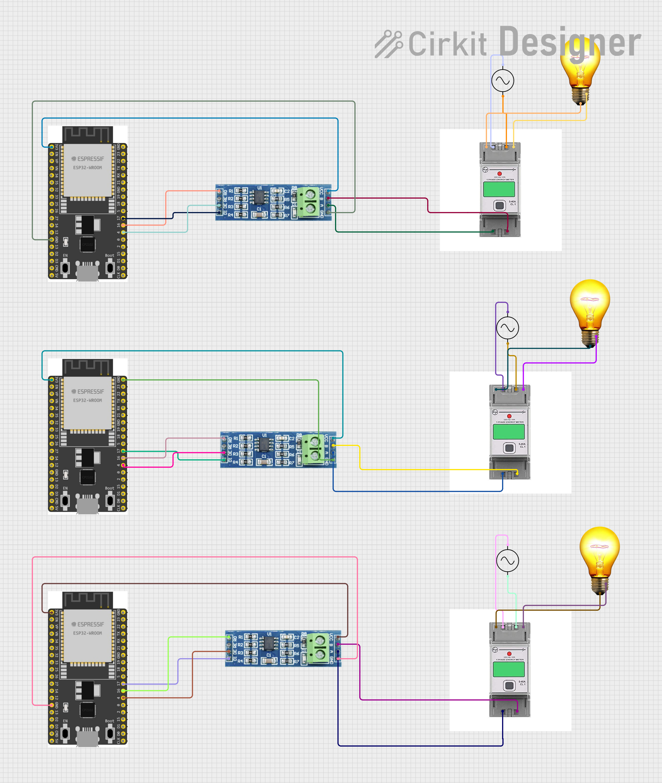
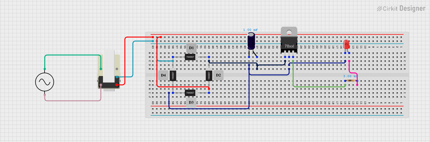
Explore Projects Built with 3 phase supply
Common Applications and Use Cases
- Powering industrial motors and heavy machinery
- Commercial HVAC systems
- Data centers and server farms
- High-power lighting systems
- Renewable energy systems (e.g., wind turbines, solar inverters)
- Electric vehicle charging stations
Technical Specifications
Key Technical Details
| Parameter | Specification |
|---|---|
| Voltage (Line-to-Line) | Typically 208V, 400V, or 480V |
| Voltage (Line-to-Neutral) | Typically 120V, 230V, or 277V |
| Frequency | 50 Hz or 60 Hz |
| Number of Phases | 3 |
| Phase Angle Difference | 120° |
| Power Factor | Typically 0.8 to 1.0 (depending on load) |
| Maximum Load Capacity | Varies based on system design |
Pin Configuration and Descriptions
A 3 phase supply typically consists of three live wires (phases) and one neutral wire. In some cases, a ground wire is also included for safety.
| Pin Name | Description |
|---|---|
| Phase 1 (L1) | First live wire carrying alternating current |
| Phase 2 (L2) | Second live wire carrying alternating current |
| Phase 3 (L3) | Third live wire carrying alternating current |
| Neutral (N) | Provides a return path for current |
| Ground (G) | Safety connection to prevent electrical hazards |
Usage Instructions
How to Use the Component in a Circuit
- Understand the Voltage and Frequency Requirements: Ensure that the equipment or load connected to the 3 phase supply matches the voltage and frequency of the supply.
- Connect the Phases: Connect the three live wires (L1, L2, L3) to the corresponding terminals of the load or equipment.
- Neutral Connection: If required, connect the neutral wire to the neutral terminal of the load.
- Grounding: Always connect the ground wire to the equipment's grounding terminal to ensure safety.
- Check Phase Sequence: Use a phase sequence meter to verify the correct phase order (L1, L2, L3). Incorrect phase sequence can cause motors to run in reverse.
- Power On: Once all connections are secure, switch on the power supply and monitor the system for proper operation.
Important Considerations and Best Practices
- Safety First: Always turn off the power supply before making or modifying connections.
- Load Balancing: Distribute the load evenly across all three phases to prevent overloading a single phase.
- Use Proper Tools: Use a multimeter or phase sequence meter to verify voltage levels and phase order.
- Circuit Protection: Install circuit breakers or fuses to protect the system from overcurrent or short circuits.
- Compliance: Ensure all installations comply with local electrical codes and standards.
Example: Connecting a 3 Phase Motor to an Arduino UNO
While an Arduino UNO cannot directly handle a 3 phase supply, it can be used to control a 3 phase motor via a motor driver or inverter. Below is an example of Arduino code to control a 3 phase motor using a PWM signal.
// Example: Controlling a 3 phase motor with Arduino UNO
// This code generates PWM signals to control a motor driver or inverter.
// Ensure proper isolation between Arduino and the high-voltage 3 phase system.

const int pwmPin1 = 9; // PWM output for Phase 1
const int pwmPin2 = 10; // PWM output for Phase 2
const int pwmPin3 = 11; // PWM output for Phase 3

void setup() {
  pinMode(pwmPin1, OUTPUT); // Set Phase 1 pin as output
  pinMode(pwmPin2, OUTPUT); // Set Phase 2 pin as output
  pinMode(pwmPin3, OUTPUT); // Set Phase 3 pin as output
}

void loop() {
  // Generate PWM signals with a phase shift of 120 degrees
  analogWrite(pwmPin1, 128); // 50% duty cycle for Phase 1
  delay(2); // Approximate phase shift for 120 degrees
  analogWrite(pwmPin2, 128); // 50% duty cycle for Phase 2
  delay(2); // Approximate phase shift for 120 degrees
  analogWrite(pwmPin3, 128); // 50% duty cycle for Phase 3
  delay(2); // Repeat the cycle
}
Note: This is a simplified example. For real-world applications, use a dedicated motor driver or inverter to handle the high voltage and current of a 3 phase motor.
Troubleshooting and FAQs
Common Issues Users Might Face
- Incorrect Phase Sequence: Motors may run in reverse or fail to start.
- Solution: Use a phase sequence meter to verify and correct the phase order.
- Uneven Load Distribution: One phase may carry more load than others, causing overheating.
- Solution: Balance the load across all three phases.
- Voltage Imbalance: Voltage levels between phases are not equal.
- Solution: Check the power source and connections for faults or loose wires.
- No Power Output: Equipment does not receive power.
- Solution: Verify all connections, circuit breakers, and fuses.
Solutions and Tips for Troubleshooting
- Use Proper Tools: Always use a multimeter, clamp meter, or phase sequence meter for diagnostics.
- Inspect Connections: Ensure all wires are securely connected and free from damage.
- Check Circuit Protection: Verify that circuit breakers and fuses are functioning correctly.
- Consult Documentation: Refer to the equipment's manual for specific troubleshooting steps.
By following this documentation, users can safely and effectively utilize a 3 phase supply for their applications.