How to Use LED Red TremaModul: Examples, Pinouts, and Specs
Introduction
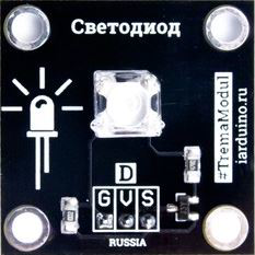
The LED Red TremaModul is a red light-emitting diode (LED) module designed for easy integration into electronic circuits. It is commonly used for status indication, visual signaling, or low-power illumination. This module is known for its energy efficiency, long lifespan, and straightforward operation, making it a popular choice for hobbyists and professionals alike.
Explore Projects Built with LED Red TremaModul
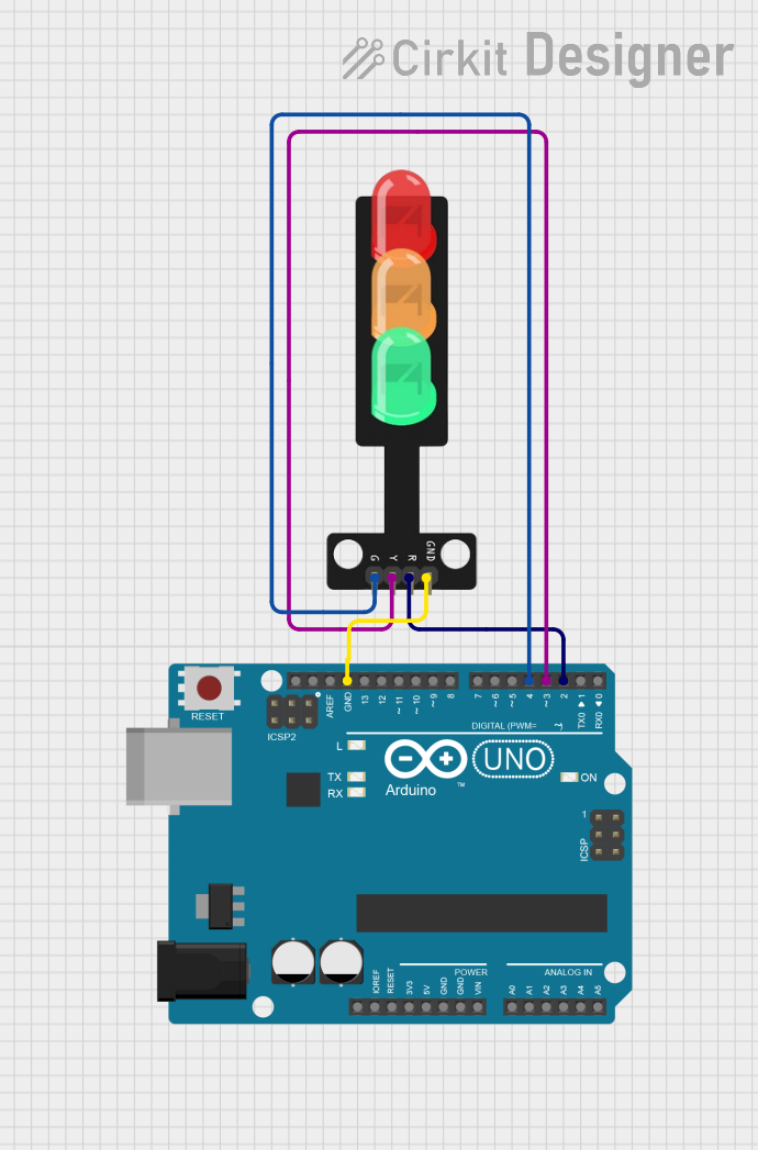
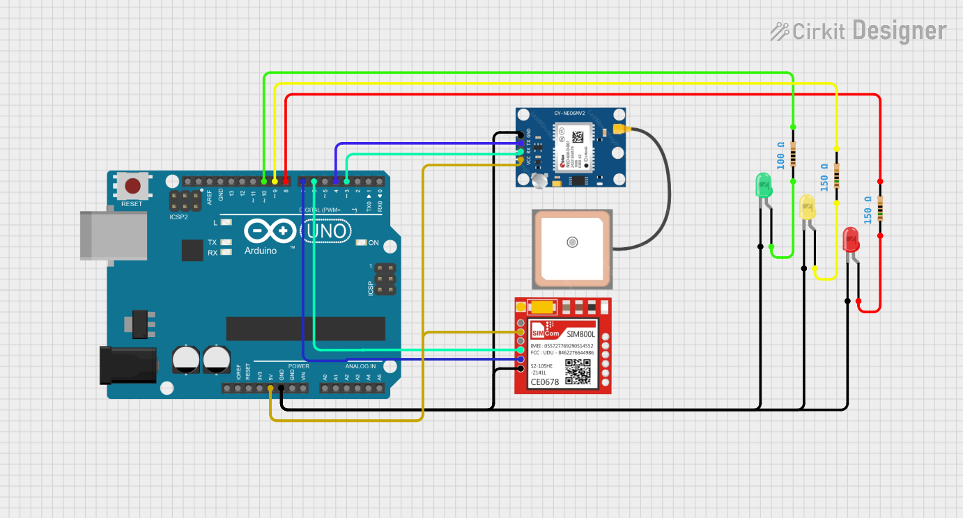
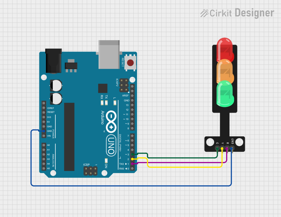
Explore Projects Built with LED Red TremaModul
Common Applications and Use Cases
- Status indicators in electronic devices
- Visual feedback in microcontroller projects
- Low-power lighting solutions
- Educational and prototyping purposes
- Debugging and testing circuits
Technical Specifications
The LED Red TremaModul is a pre-assembled module that includes a red LED and a current-limiting resistor, making it ready to use without requiring additional components.
Key Technical Details
- Operating Voltage: 3.3V to 5V DC
- Forward Current: 20mA (typical)
- Wavelength: ~620-630nm (red light)
- Brightness: ~100-200 mcd (typical)
- Power Consumption: ~0.1W
- Dimensions: 15mm x 10mm x 5mm (approx.)
- Connector Type: 3-pin header (VCC, GND, Signal)
Pin Configuration and Descriptions
The LED Red TremaModul has a 3-pin interface for easy connection to microcontrollers or other circuits. Below is the pinout description:
| Pin | Label | Description |
|---|---|---|
| 1 | VCC | Power supply input (3.3V to 5V DC) |
| 2 | GND | Ground connection |
| 3 | Signal | Control signal to turn the LED on/off |
Usage Instructions
How to Use the Component in a Circuit
- Power Connection: Connect the VCC pin to a 3.3V or 5V power source and the GND pin to the ground of your circuit.
- Control Signal: Use the Signal pin to control the LED. This pin can be connected to a microcontroller's GPIO pin or a simple switch.
- Resistor Pre-Installed: The module includes a built-in current-limiting resistor, so no external resistor is required.
Example Circuit with Arduino UNO
Below is an example of how to connect and control the LED Red TremaModul using an Arduino UNO:
Circuit Connections
- Connect the VCC pin of the module to the 5V pin on the Arduino.
- Connect the GND pin of the module to the GND pin on the Arduino.
- Connect the Signal pin of the module to digital pin 8 on the Arduino.
Arduino Code Example
// LED Red TremaModul Example Code
// This code blinks the LED connected to digital pin 8 on the Arduino UNO.

const int ledPin = 8; // Define the pin connected to the Signal pin of the module

void setup() {
  pinMode(ledPin, OUTPUT); // Set the pin as an output
}

void loop() {
  digitalWrite(ledPin, HIGH); // Turn the LED on
  delay(1000);               // Wait for 1 second
  digitalWrite(ledPin, LOW);  // Turn the LED off
  delay(1000);               // Wait for 1 second
}
Important Considerations and Best Practices
- Voltage Range: Ensure the input voltage is within the specified range (3.3V to 5V) to avoid damaging the module.
- Polarity: Double-check the connections to avoid reversing the polarity, which could damage the LED.
- Signal Control: When using a microcontroller, configure the GPIO pin as an output to control the LED properly.
- Avoid Overcurrent: Do not bypass the built-in resistor, as it protects the LED from excessive current.
Troubleshooting and FAQs
Common Issues and Solutions
LED Does Not Light Up:
- Verify that the VCC and GND connections are correct.
- Ensure the Signal pin is receiving a HIGH signal (e.g., 5V from a microcontroller).
- Check the power supply voltage to ensure it is within the operating range.
LED Flickers or Is Dim:
- Ensure a stable power supply is used.
- Check for loose or poor connections in the circuit.
Module Overheats:
- Verify that the input voltage does not exceed 5V.
- Avoid bypassing the built-in resistor.
FAQs
Q: Can I use the LED Red TremaModul with a 3.3V microcontroller?
A: Yes, the module is compatible with both 3.3V and 5V systems.
Q: Do I need an external resistor for this module?
A: No, the module includes a built-in current-limiting resistor, so no additional resistor is required.
Q: Can I control the LED brightness?
A: Yes, you can use PWM (Pulse Width Modulation) on the Signal pin to adjust the brightness.
Q: Is the module suitable for outdoor use?
A: The module is not weatherproof and should be used in dry, indoor environments unless additional protection is provided.
By following this documentation, you can effectively integrate the LED Red TremaModul into your projects and troubleshoot any issues that may arise.