Cirkit Designer Logo
Cirkit Designer
Your all-in-one circuit design IDE
Home / 
Component Documentation

How to Use Noise Filter: Examples, Pinouts, and Specs

Image of Noise Filter
Cirkit Designer LogoDesign with Noise Filter in Cirkit Designer

Introduction

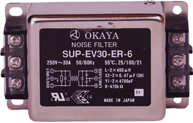
The OKAYA SUP-EV30-ER-6 is a noise filter designed to suppress electromagnetic interference (EMI) and radio frequency interference (RFI) in electrical systems. This component is essential in applications where signal integrity is critical, and unwanted noise can degrade performance. Common applications include audio equipment, power supplies, and communication systems.

Explore Projects Built with Noise Filter

Use Cirkit Designer to design, explore, and prototype these projects online. Some projects support real-time simulation. Click "Open Project" to start designing instantly!
Audio Signal Conditioning Circuit with 3.5mm Jacks and Passive Components
Image of BA: A project utilizing Noise Filter in a practical application
This circuit appears to be an audio signal processing or filtering circuit, utilizing multiple 3.5mm jacks for input and output connections, resistors, and capacitors to form various RC (resistor-capacitor) networks. The configuration suggests it could be used for tasks such as audio signal conditioning, noise filtering, or impedance matching.
Cirkit Designer LogoOpen Project in Cirkit Designer
Arduino UNO-Based Noise Cancellation System with Dual KY-037 Microphones and Op-Amp
Image of Adaptive Noise Cancellation: A project utilizing Noise Filter in a practical application
This circuit uses an Arduino UNO to read analog signals from two KY-037 microphones, which are processed through a Sparkfun Configurable OpAmp Board for basic noise cancellation. The Arduino subtracts the reference microphone signal from the primary microphone signal and outputs the filtered result to the Serial Monitor.
Cirkit Designer LogoOpen Project in Cirkit Designer
Op-Amp Based Signal Amplification and Analysis Circuit
Image of Lab 3: Non-Inverting Unity Gain Op-Amp Schematic: A project utilizing Noise Filter in a practical application
This circuit is an active filter or oscillator circuit utilizing a 741 operational amplifier with feedback components (resistor and capacitor) to shape the frequency response. A function generator provides the input signal, and an oscilloscope is used to observe the circuit's output. The circuit is powered by a dedicated power supply.
Cirkit Designer LogoOpen Project in Cirkit Designer
Arduino UNO Noise Detection System with LCD Display
Image of sample: A project utilizing Noise Filter in a practical application
This circuit uses an Arduino UNO to read sound levels from a sound sensor and display the noise status on a 16x2 I2C LCD screen. The Arduino processes the analog input from the sound sensor and updates the LCD to indicate whether the environment is quiet or noisy based on a predefined threshold.
Cirkit Designer LogoOpen Project in Cirkit Designer

Explore Projects Built with Noise Filter

Use Cirkit Designer to design, explore, and prototype these projects online. Some projects support real-time simulation. Click "Open Project" to start designing instantly!
Image of BA: A project utilizing Noise Filter in a practical application
Audio Signal Conditioning Circuit with 3.5mm Jacks and Passive Components
This circuit appears to be an audio signal processing or filtering circuit, utilizing multiple 3.5mm jacks for input and output connections, resistors, and capacitors to form various RC (resistor-capacitor) networks. The configuration suggests it could be used for tasks such as audio signal conditioning, noise filtering, or impedance matching.
Cirkit Designer LogoOpen Project in Cirkit Designer
Image of Adaptive Noise Cancellation: A project utilizing Noise Filter in a practical application
Arduino UNO-Based Noise Cancellation System with Dual KY-037 Microphones and Op-Amp
This circuit uses an Arduino UNO to read analog signals from two KY-037 microphones, which are processed through a Sparkfun Configurable OpAmp Board for basic noise cancellation. The Arduino subtracts the reference microphone signal from the primary microphone signal and outputs the filtered result to the Serial Monitor.
Cirkit Designer LogoOpen Project in Cirkit Designer
Image of Lab 3: Non-Inverting Unity Gain Op-Amp Schematic: A project utilizing Noise Filter in a practical application
Op-Amp Based Signal Amplification and Analysis Circuit
This circuit is an active filter or oscillator circuit utilizing a 741 operational amplifier with feedback components (resistor and capacitor) to shape the frequency response. A function generator provides the input signal, and an oscilloscope is used to observe the circuit's output. The circuit is powered by a dedicated power supply.
Cirkit Designer LogoOpen Project in Cirkit Designer
Image of sample: A project utilizing Noise Filter in a practical application
Arduino UNO Noise Detection System with LCD Display
This circuit uses an Arduino UNO to read sound levels from a sound sensor and display the noise status on a 16x2 I2C LCD screen. The Arduino processes the analog input from the sound sensor and updates the LCD to indicate whether the environment is quiet or noisy based on a predefined threshold.
Cirkit Designer LogoOpen Project in Cirkit Designer

Technical Specifications

Key Technical Details

  • Rated Voltage: 250VAC
  • Rated Current: 6A
  • Operating Frequency: 50/60Hz
  • Insertion Loss: Min. 30dB (in the 1MHz to 30MHz frequency range)
  • Operating Temperature Range: -25°C to +85°C
  • Safety Standards: UL, CSA, VDE approved

Pin Configuration and Descriptions

Pin Number Description Notes
1 Line (L) Connect to the phase line
2 Neutral (N) Connect to the neutral line
3 Ground (Earth) Connect to the earth grounding
4 Output Line (L') Filtered phase line
5 Output Neutral (N') Filtered neutral line
6 Case Metal case (grounded)

Usage Instructions

How to Use the Component in a Circuit

  1. Integration: The noise filter should be installed as close as possible to the power entry point of the device.
  2. Wiring: Connect the input lines (L and N) to the power source, and the output lines (L' and N') to the device.
  3. Grounding: Ensure the ground pin is properly connected to the earth ground for optimal performance.

Important Considerations and Best Practices

  • Load Rating: Do not exceed the rated current of 6A to prevent overheating and potential damage.
  • Temperature: Operate within the specified temperature range for safety and reliability.
  • Mounting: Secure the filter firmly to the chassis to maintain grounding integrity.
  • Certifications: Verify that the installation complies with UL, CSA, and VDE standards.

Troubleshooting and FAQs

Common Issues

  • Inadequate Noise Suppression: Ensure the filter is correctly installed and the ground connection is secure.
  • Overheating: Check if the current rating is exceeded or if there is inadequate ventilation around the filter.

Solutions and Tips

  • Recheck Wiring: Confirm that all connections are correct and secure.
  • Inspect for Damage: Look for any signs of physical damage or overheating on the filter.
  • Consult Manufacturer: If problems persist, contact OKAYA for further assistance.

FAQs

Q: Can this filter be used with DC applications? A: No, the SUP-EV30-ER-6 is designed for AC applications only.

Q: What is the purpose of the metal case? A: The metal case provides shielding and should be grounded to enhance the filter's effectiveness.

Q: Is there a need for additional filtering components? A: This depends on the specific application and the level of noise suppression required. The SUP-EV30-ER-6 may be sufficient for many applications, but additional filtering stages can be added if necessary.

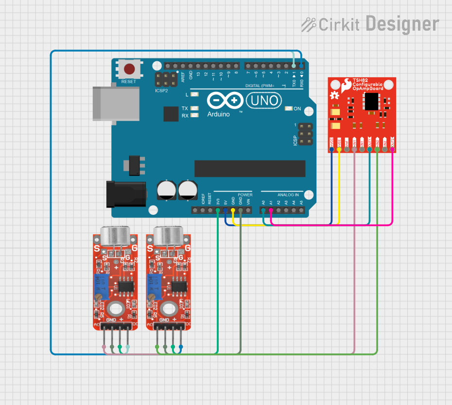
Example Connection with Arduino UNO

The OKAYA SUP-EV30-ER-6 is not typically used directly with an Arduino UNO, as it is designed for AC power line filtering. However, if you are powering an Arduino project from an AC source and require noise suppression, you would place the noise filter between the AC power source and the power supply converting AC to the DC voltage required by the Arduino.

// No direct code is associated with the noise filter as it is a passive component.
// However, if you are using a power supply with the Arduino that is connected to an AC source,
// you can install the noise filter at the AC input stage of the power supply.

Remember, the noise filter is a passive component and does not require any programming or interaction with the Arduino's software. It is purely for ensuring the quality of the power supply to the electronic components.