
How to Use 3s 20A BMS: Examples, Pinouts, and Specs
 Design with 3s 20A BMS in Cirkit Designer
Introduction
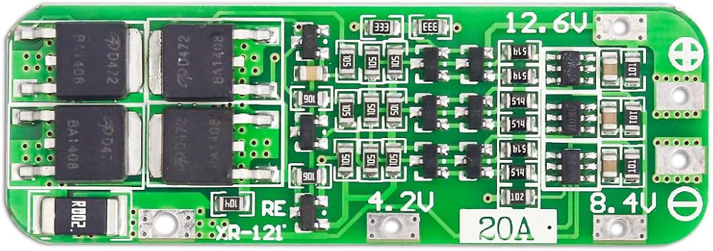
The 3S 20A Battery Management System (BMS) is a critical component for managing 3-cell series lithium-ion battery packs. It ensures the safe operation of the battery pack by monitoring individual cell voltages and temperatures, balancing the cells during charging and discharging, and protecting against overcharge, over-discharge, overcurrent, and short circuits. This BMS is capable of handling a maximum continuous current of 20A, making it suitable for medium-power applications.
Explore Projects Built with 3s 20A BMS
 Open Project in Cirkit Designer
 Open Project in Cirkit Designer
 Open Project in Cirkit Designer
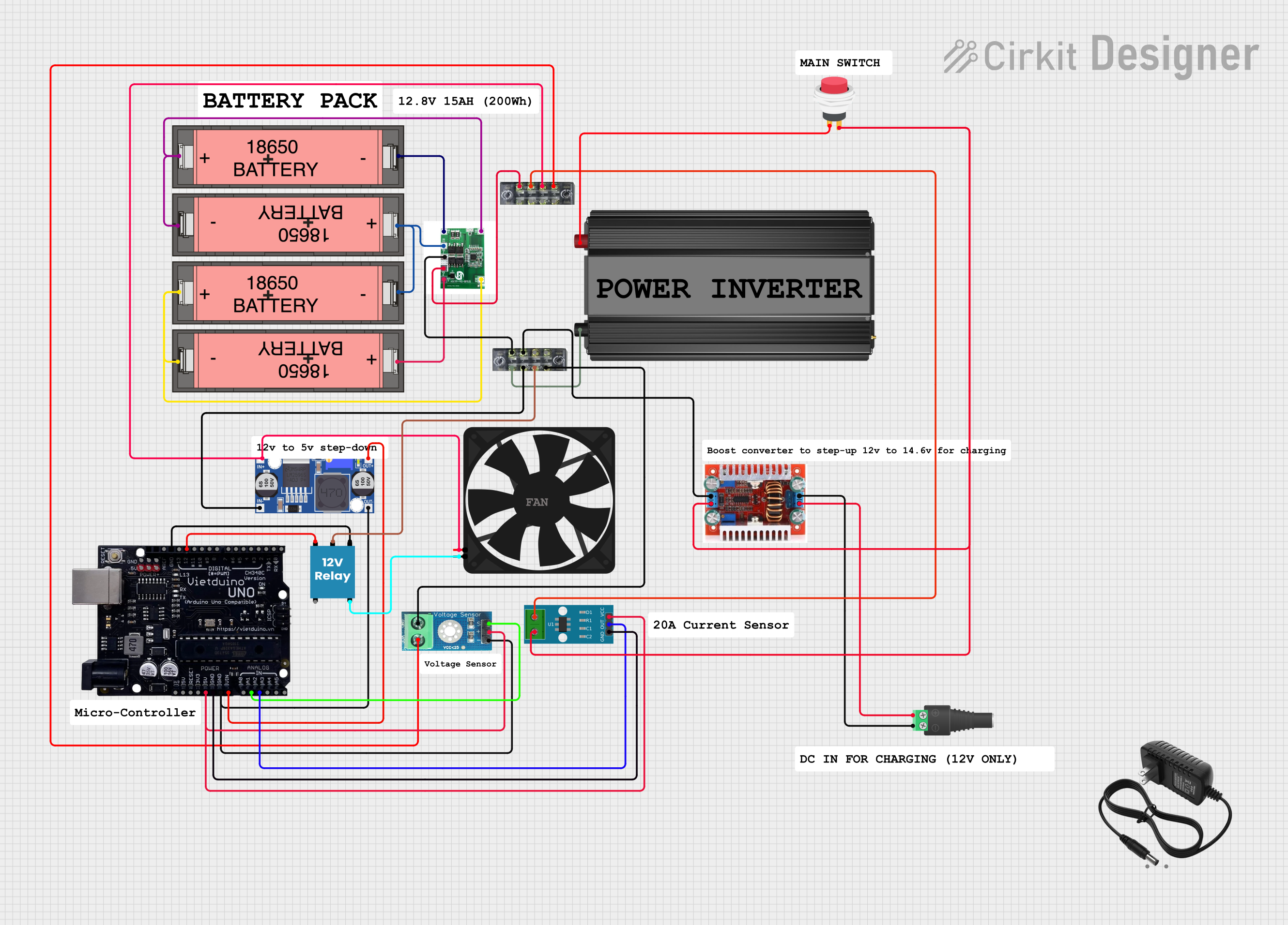 Open Project in Cirkit Designer
Explore Projects Built with 3s 20A BMS
Open Project in Cirkit DesignerOpen Project in Cirkit DesignerOpen Project in Cirkit DesignerOpen Project in Cirkit DesignerCommon Applications and Use Cases
- Electric bicycles and scooters
- Portable power banks
- Solar energy storage systems
- Robotics and DIY electronics projects
- Uninterruptible Power Supplies (UPS)
Technical Specifications
Below are the key technical details of the 3S 20A BMS:
| Parameter | Value |
|---|---|
| Battery Configuration | 3-cell series (3S) lithium-ion |
| Maximum Continuous Current | 20A |
| Overcharge Protection | 4.25V ± 0.05V per cell |
| Over-discharge Protection | 2.8V ± 0.05V per cell |
| Balancing Voltage | 4.2V per cell |
| Balancing Current | 30mA (typical) |
| Operating Temperature | -20°C to 60°C |
| Dimensions | ~45mm x 60mm x 3mm |
Pin Configuration and Descriptions
The 3S 20A BMS typically has the following pin connections:
| Pin Name | Description |
|---|---|
| B- | Battery pack negative terminal |
| B1 | Connection to the positive terminal of the first cell |
| B2 | Connection to the positive terminal of the second cell |
| B+ | Battery pack positive terminal |
| P- | Power output negative terminal (connect to load or charger negative terminal) |
| P+ | Power output positive terminal (connect to load or charger positive terminal) |
Usage Instructions
How to Use the 3S 20A BMS in a Circuit
Connect the Battery Pack:
- Connect the B- pin to the negative terminal of the battery pack.
- Connect the B1 pin to the positive terminal of the first cell.
- Connect the B2 pin to the positive terminal of the second cell.
- Connect the B+ pin to the positive terminal of the battery pack.
Connect the Load and Charger:
- Connect the P- pin to the negative terminal of the load or charger.
- Connect the P+ pin to the positive terminal of the load or charger.
Verify Connections:
- Double-check all connections to ensure they are secure and correct.
- Ensure the battery pack voltage matches the BMS specifications.
Power On:
- Once all connections are verified, the BMS will automatically start monitoring and protecting the battery pack.
Important Considerations and Best Practices
- Cell Matching: Ensure all cells in the battery pack have similar capacities and internal resistances to avoid imbalance.
- Heat Dissipation: If operating near the maximum current (20A), ensure proper ventilation or heat sinking to prevent overheating.
- Avoid Overloading: Do not exceed the maximum current rating of 20A to prevent damage to the BMS.
- Wiring: Use appropriately rated wires for the current to avoid voltage drops and overheating.
Arduino Integration Example
While the 3S 20A BMS does not directly interface with an Arduino, you can monitor the battery pack's voltage using an Arduino and a voltage divider circuit. Below is an example code snippet for monitoring the total battery voltage:
// Arduino code to monitor battery voltage using a voltage divider
const int voltagePin = A0; // Analog pin connected to the voltage divider
const float resistorRatio = 5.7; // Ratio of the voltage divider resistors
const float referenceVoltage = 5.0; // Arduino reference voltage (5V for most boards)

void setup() {
  Serial.begin(9600); // Initialize serial communication
}

void loop() {
  int analogValue = analogRead(voltagePin); // Read the analog input
  float batteryVoltage = (analogValue / 1023.0) * referenceVoltage * resistorRatio;

  // Print the battery voltage to the Serial Monitor
  Serial.print("Battery Voltage: ");
  Serial.print(batteryVoltage);
  Serial.println(" V");

  delay(1000); // Wait for 1 second before the next reading
}
Note: Use appropriately rated resistors for the voltage divider to ensure the input voltage to the Arduino does not exceed 5V.
Troubleshooting and FAQs
Common Issues and Solutions
BMS Not Powering On:
- Cause: Incorrect wiring or insufficient battery voltage.
- Solution: Verify all connections and ensure the battery pack voltage is within the BMS operating range.
Battery Pack Not Charging:
- Cause: Charger voltage is too low or connections are incorrect.
- Solution: Ensure the charger voltage matches the battery pack's requirements and check the P+ and P- connections.
Overheating During Operation:
- Cause: Exceeding the maximum current rating or poor ventilation.
- Solution: Reduce the load current and ensure proper heat dissipation.
Cells Not Balancing:
- Cause: Significant mismatch in cell capacities or damaged cells.
- Solution: Replace mismatched or damaged cells and ensure all cells are balanced before connecting to the BMS.
FAQs
Q: Can I use this BMS for a 4-cell battery pack?
A: No, this BMS is specifically designed for 3-cell series (3S) lithium-ion battery packs. Using it with a 4-cell pack may result in improper operation or damage.Q: What happens if one cell is over-discharged?
A: The BMS will disconnect the load to protect the cell from further damage. Replace or recharge the cell before reconnecting.Q: Can I use this BMS with lithium iron phosphate (LiFePO4) batteries?
A: No, this BMS is designed for lithium-ion batteries with a nominal voltage of 3.7V per cell. LiFePO4 batteries have different voltage characteristics.Q: How do I know if the BMS is balancing the cells?
A: During charging, the BMS will balance the cells when their voltages exceed 4.2V. You can measure the individual cell voltages to confirm.
By following this documentation, you can safely and effectively use the 3S 20A BMS in your projects.