
How to Use 5 mm RGB LED, Common Cathode (R-B-G Pin Order): Examples, Pinouts, and Specs
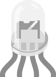
 Design with 5 mm RGB LED, Common Cathode (R-B-G Pin Order) in Cirkit Designer
Introduction
The 5 mm RGB LED, Common Cathode, is a versatile light-emitting diode that combines red, blue, and green LEDs into a single package. This component allows users to create a wide range of colors by varying the intensity of each LED. The "common cathode" configuration means that all three LEDs share a single cathode (negative) pin, while the anodes (positive pins) are separate for each color.
Explore Projects Built with 5 mm RGB LED, Common Cathode (R-B-G Pin Order)
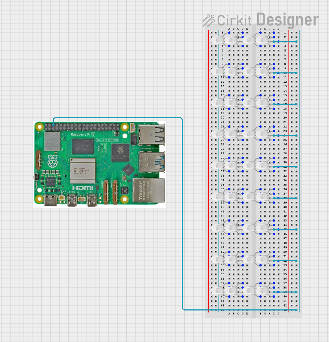 Open Project in Cirkit Designer
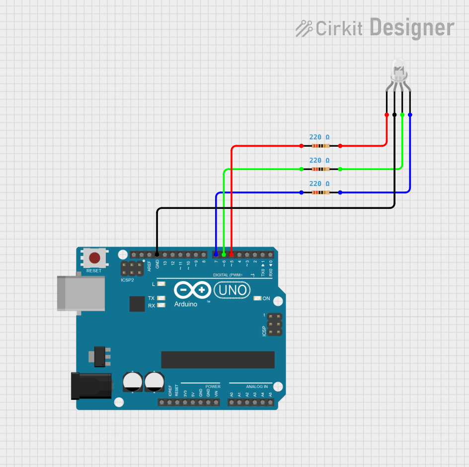 Open Project in Cirkit Designer
 Open Project in Cirkit Designer
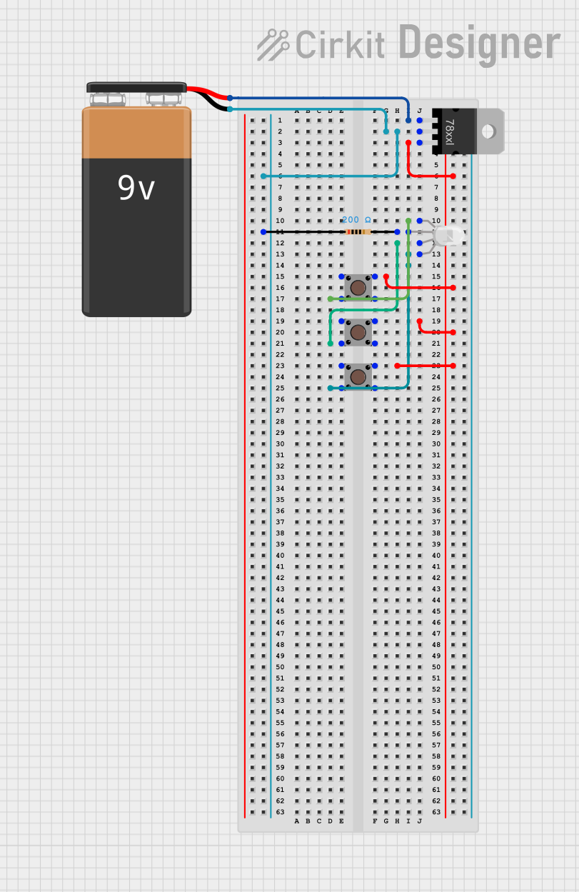 Open Project in Cirkit Designer
Explore Projects Built with 5 mm RGB LED, Common Cathode (R-B-G Pin Order)
Open Project in Cirkit DesignerOpen Project in Cirkit DesignerOpen Project in Cirkit DesignerOpen Project in Cirkit DesignerCommon Applications and Use Cases
- Decorative lighting and displays
- Status indicators
- DIY electronics projects
- Arduino and microcontroller-based projects
- Mood lighting and color mixing experiments
Technical Specifications
- Package Size: 5 mm diameter
- Configuration: Common Cathode
- Forward Voltage:
- Red: 2.0V - 2.4V
- Green: 3.0V - 3.4V
- Blue: 3.0V - 3.4V
- Forward Current: 20 mA (per color)
- Maximum Power Dissipation: 75 mW (per color)
- Viewing Angle: 20° - 30°
- Pin Order: Red (R), Blue (B), Green (G), Cathode (Common)
Pin Configuration and Descriptions
| Pin Number | Pin Name | Description |
|---|---|---|
| 1 | Red (R) | Positive terminal for the red LED |
| 2 | Cathode | Common negative terminal for all LEDs |
| 3 | Blue (B) | Positive terminal for the blue LED |
| 4 | Green (G) | Positive terminal for the green LED |
Usage Instructions
How to Use the Component in a Circuit
- Connect the Cathode: Connect the cathode pin (Pin 2) to the ground (GND) of your circuit.
- Current Limiting Resistors: Use a resistor in series with each anode (R, B, G) to limit the current and prevent damage to the LEDs. Calculate the resistor value using Ohm's Law: [ R = \frac{V_{supply} - V_{forward}}{I_{forward}} ] For example, with a 5V supply and a forward voltage of 2.0V for the red LED: [ R = \frac{5V - 2.0V}{0.02A} = 150 , \Omega ]
- Control the LEDs: Connect the anodes to a microcontroller (e.g., Arduino) or switches to control the brightness and color.
Important Considerations and Best Practices
- Resistor Selection: Always use appropriate resistors to avoid overdriving the LEDs.
- PWM Control: Use Pulse Width Modulation (PWM) to adjust the brightness of each LED and mix colors.
- Heat Management: Avoid exceeding the maximum power dissipation to prevent overheating.
- Pin Identification: Double-check the pin order (R-B-G) before connecting to avoid incorrect wiring.
Example: Connecting to an Arduino UNO
Below is an example of how to connect and control the 5 mm RGB LED using an Arduino UNO.
Circuit Diagram
- Connect the cathode (Pin 2) to GND.
- Connect the red, blue, and green anodes (Pins 1, 3, and 4) to Arduino digital PWM pins (e.g., D9, D10, D11) through 150 Ω resistors.
Arduino Code
// Define the RGB LED pins
const int redPin = 9;   // Red LED connected to pin D9
const int bluePin = 10; // Blue LED connected to pin D10
const int greenPin = 11; // Green LED connected to pin D11

void setup() {
  // Set the RGB pins as outputs
  pinMode(redPin, OUTPUT);
  pinMode(bluePin, OUTPUT);
  pinMode(greenPin, OUTPUT);
}

void loop() {
  // Example: Cycle through red, green, and blue colors
  setColor(255, 0, 0); // Red
  delay(1000);         // Wait 1 second
  setColor(0, 255, 0); // Green
  delay(1000);         // Wait 1 second
  setColor(0, 0, 255); // Blue
  delay(1000);         // Wait 1 second
}

// Function to set the RGB LED color
void setColor(int redValue, int greenValue, int blueValue) {
  analogWrite(redPin, redValue);   // Set red brightness (0-255)
  analogWrite(greenPin, greenValue); // Set green brightness (0-255)
  analogWrite(bluePin, blueValue);  // Set blue brightness (0-255)
}
Troubleshooting and FAQs
Common Issues
LED Not Lighting Up:
- Check the wiring and ensure the cathode is connected to GND.
- Verify that the resistors are correctly calculated and connected.
- Ensure the power supply voltage matches the LED's requirements.
Incorrect Colors:
- Double-check the pin connections (R-B-G order).
- Verify the PWM values in your code.
LED Flickering:
- Ensure stable power supply and proper grounding.
- Check for loose connections or faulty resistors.
LED Overheating:
- Confirm that the current-limiting resistors are of the correct value.
- Avoid exceeding the maximum forward current (20 mA per color).
FAQs
Q: Can I use the RGB LED without a microcontroller?
A: Yes, you can use switches or potentiometers to manually control the brightness of each LED.
Q: How do I create custom colors?
A: Use PWM to adjust the brightness of each LED. For example, setting red to 128, green to 64, and blue to 255 will create a unique color.
Q: Can I connect the RGB LED directly to a power source?
A: No, always use current-limiting resistors to prevent damage to the LEDs.
Q: What happens if I reverse the polarity?
A: The LED will not light up, but it is unlikely to be damaged unless excessive voltage is applied. Always double-check the pin configuration.