How to Use button switch: Examples, Pinouts, and Specs
Introduction
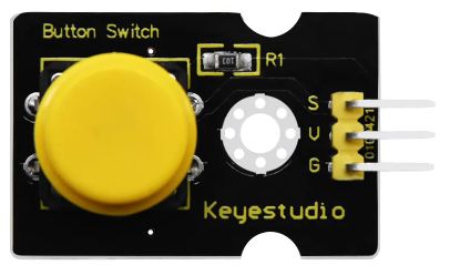
A button switch, manufactured by Keyestudio (Part ID: Switch Module), is a mechanical device that allows users to open or close an electrical circuit by pressing a button. This simple yet versatile component is widely used in various applications, such as turning devices on or off, triggering events in microcontroller projects, or acting as an input device in user interfaces.
Explore Projects Built with button switch

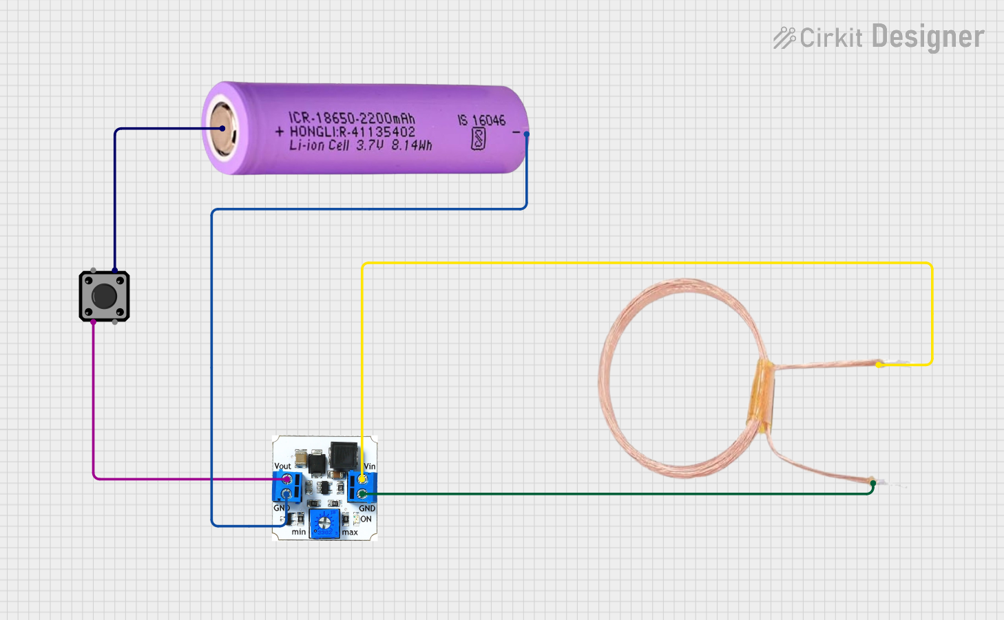
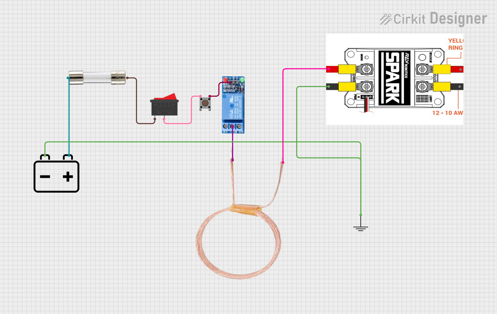

Explore Projects Built with button switch
Common Applications and Use Cases
- Powering devices on or off
- Input control for microcontroller projects (e.g., Arduino, Raspberry Pi)
- Triggering events in electronic circuits
- User interface buttons for consumer electronics
- Reset switches in embedded systems
Technical Specifications
The Keyestudio button switch module is designed for ease of use in prototyping and educational projects. Below are its key technical details:
Key Technical Details
- Operating Voltage: 3.3V to 5V
- Current Rating: ≤ 50mA
- Switch Type: Momentary push-button (normally open)
- Debouncing: Not included (external debouncing may be required)
- Dimensions: 20mm x 15mm x 10mm (approx.)
- Mounting: PCB-compatible with solderable pins
Pin Configuration and Descriptions
The button switch module has a simple 3-pin configuration:
| Pin | Label | Description |
|---|---|---|
| 1 | GND | Ground connection |
| 2 | VCC | Power supply (3.3V or 5V) |
| 3 | SIG | Signal output (HIGH when pressed, LOW otherwise) |
Usage Instructions
The Keyestudio button switch module is straightforward to use in electronic circuits. Below are the steps and best practices for integrating it into your project.
How to Use the Button Switch in a Circuit
Connect the Pins:
- Connect the GND pin to the ground of your circuit.
- Connect the VCC pin to a 3.3V or 5V power source.
- Connect the SIG pin to the input pin of your microcontroller or circuit.
Read the Signal:
- When the button is pressed, the SIG pin outputs a HIGH signal (equal to VCC).
- When the button is released, the SIG pin outputs a LOW signal (0V).
Debouncing:
- Since the button switch does not include built-in debouncing, you may experience multiple signal changes (bouncing) when the button is pressed or released.
- Use a software or hardware debouncing method to ensure stable signal readings.
Example: Using the Button Switch with an Arduino UNO
Below is an example of how to use the button switch module with an Arduino UNO to turn an LED on and off:
// Define pin connections
const int buttonPin = 2;  // SIG pin of the button switch connected to digital pin 2
const int ledPin = 13;    // Built-in LED on Arduino UNO

// Variable to store button state
int buttonState = 0;

void setup() {
  pinMode(buttonPin, INPUT);  // Set button pin as input
  pinMode(ledPin, OUTPUT);   // Set LED pin as output
}

void loop() {
  // Read the state of the button
  buttonState = digitalRead(buttonPin);

  // If the button is pressed, turn on the LED
  if (buttonState == HIGH) {
    digitalWrite(ledPin, HIGH);  // Turn on LED
  } else {
    digitalWrite(ledPin, LOW);   // Turn off LED
  }
}
Important Considerations and Best Practices
- Power Supply: Ensure the module is powered within its operating voltage range (3.3V to 5V).
- Debouncing: Use a capacitor or software logic to handle signal bouncing for reliable operation.
- Signal Level: Verify that the signal output (HIGH/LOW) is compatible with your microcontroller's input voltage levels.
- Pull-up Resistor: If the module does not include an internal pull-up resistor, configure the microcontroller pin with an internal pull-up or add an external resistor.
Troubleshooting and FAQs
Common Issues and Solutions
Button Press Not Detected:
- Cause: Loose or incorrect wiring.
- Solution: Double-check all connections, ensuring the SIG pin is connected to the correct input pin.
Unstable Signal (Bouncing):
- Cause: Mechanical bouncing of the button contacts.
- Solution: Implement a debouncing circuit (e.g., RC filter) or use software debouncing in your code.
No Signal Output:
- Cause: Incorrect power supply or damaged module.
- Solution: Verify the VCC and GND connections and ensure the power supply is within the specified range.
Signal Always HIGH or LOW:
- Cause: Faulty button switch or incorrect pull-up/pull-down configuration.
- Solution: Test the button switch with a multimeter and check for proper pull-up or pull-down resistor setup.
FAQs
Q1: Can I use the button switch module with a 3.3V microcontroller?
A1: Yes, the module is compatible with both 3.3V and 5V systems.
Q2: Do I need an external pull-up resistor?
A2: The module may already include a pull-up resistor. If not, you can enable the internal pull-up resistor on your microcontroller or add an external one.
Q3: How do I debounce the button in software?
A3: You can use a delay or a state-checking algorithm in your code to filter out bouncing signals.
Q4: Can I use this module for long-term applications?
A4: Yes, but ensure the button is not exposed to excessive mechanical stress or environmental factors like moisture.
By following this documentation, you can effectively integrate the Keyestudio button switch module into your projects and troubleshoot any issues that arise.