Cirkit Designer Logo
Cirkit Designer
Your all-in-one circuit design IDE
Home / 
Component Documentation

How to Use connector: Examples, Pinouts, and Specs

Image of connector
Cirkit Designer LogoDesign with connector in Cirkit Designer

Introduction

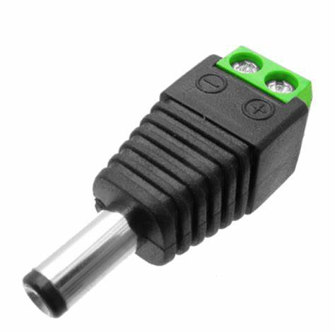
A connector is a device used to join electrical circuits together, ensuring a secure and reliable connection. Connectors are essential components in various electronic applications, providing a means to connect different parts of a circuit without the need for permanent soldering. They are widely used in consumer electronics, automotive systems, industrial machinery, and more.

Explore Projects Built with connector

Use Cirkit Designer to design, explore, and prototype these projects online. Some projects support real-time simulation. Click "Open Project" to start designing instantly!
5-Pin Connector Synchronization Circuit
Image of UMB_Cable: A project utilizing connector in a practical application
This circuit consists of four 5-pin connectors, where two of the connectors are fully interconnected pin-to-pin. The purpose of this setup could be to create a parallel connection between the two 5-pin connectors, possibly for signal distribution or redundancy.
Cirkit Designer LogoOpen Project in Cirkit Designer
Pushbutton-Controlled Interface with 40-Pin Connector and UBS Power Supply
Image of connect 4: A project utilizing connector in a practical application
This circuit consists of a 40-pin connector interfacing with four pushbuttons and a UBS power supply. The pushbuttons are used as inputs to the connector, which then relays the signals to other components or systems. The UBS power supply provides the necessary 24V power to the pushbuttons and the common ground for the circuit.
Cirkit Designer LogoOpen Project in Cirkit Designer
Peltier-Controlled Thermal Management System with SPST Switch
Image of Mini car refrigerator circuit: A project utilizing connector in a practical application
This circuit consists of multiple Peltier modules and fans connected in parallel to a digital power supply, with a rocker switch (SPST) controlling the power flow to one of the Peltier modules and multiple fans. The 2.1mm Barrel Jack with Terminal Block serves as the power input connector, and the rocker switch allows for selective enabling or disabling of the connected devices. The circuit is designed to provide cooling or heating through the Peltier modules while the fans assist in heat dissipation or air circulation.
Cirkit Designer LogoOpen Project in Cirkit Designer
Dual Motor Control System with DPDT Switches and Planetary Gearbox Motors
Image of LEAD SCREW : A project utilizing connector in a practical application
This circuit features two DPDT switches that control the direction of two MRB Planetary gearbox motors. The switches are connected to a connector, allowing for external control inputs to change the motor directions.
Cirkit Designer LogoOpen Project in Cirkit Designer

Explore Projects Built with connector

Use Cirkit Designer to design, explore, and prototype these projects online. Some projects support real-time simulation. Click "Open Project" to start designing instantly!
Image of UMB_Cable: A project utilizing connector in a practical application
5-Pin Connector Synchronization Circuit
This circuit consists of four 5-pin connectors, where two of the connectors are fully interconnected pin-to-pin. The purpose of this setup could be to create a parallel connection between the two 5-pin connectors, possibly for signal distribution or redundancy.
Cirkit Designer LogoOpen Project in Cirkit Designer
Image of connect 4: A project utilizing connector in a practical application
Pushbutton-Controlled Interface with 40-Pin Connector and UBS Power Supply
This circuit consists of a 40-pin connector interfacing with four pushbuttons and a UBS power supply. The pushbuttons are used as inputs to the connector, which then relays the signals to other components or systems. The UBS power supply provides the necessary 24V power to the pushbuttons and the common ground for the circuit.
Cirkit Designer LogoOpen Project in Cirkit Designer
Image of Mini car refrigerator circuit: A project utilizing connector in a practical application
Peltier-Controlled Thermal Management System with SPST Switch
This circuit consists of multiple Peltier modules and fans connected in parallel to a digital power supply, with a rocker switch (SPST) controlling the power flow to one of the Peltier modules and multiple fans. The 2.1mm Barrel Jack with Terminal Block serves as the power input connector, and the rocker switch allows for selective enabling or disabling of the connected devices. The circuit is designed to provide cooling or heating through the Peltier modules while the fans assist in heat dissipation or air circulation.
Cirkit Designer LogoOpen Project in Cirkit Designer
Image of LEAD SCREW : A project utilizing connector in a practical application
Dual Motor Control System with DPDT Switches and Planetary Gearbox Motors
This circuit features two DPDT switches that control the direction of two MRB Planetary gearbox motors. The switches are connected to a connector, allowing for external control inputs to change the motor directions.
Cirkit Designer LogoOpen Project in Cirkit Designer

Technical Specifications

Key Technical Details

Parameter Value
Voltage Rating 250V AC/DC
Current Rating 10A
Contact Resistance ≤ 20mΩ
Insulation Resistance ≥ 1000MΩ
Operating Temperature -40°C to +105°C
Material Plastic housing, metal pins

Pin Configuration and Descriptions

Pin Number Description
1 Ground (GND)
2 Power Supply (VCC)
3 Signal Line 1 (SIG1)
4 Signal Line 2 (SIG2)

Usage Instructions

How to Use the Connector in a Circuit

  1. Identify the Pins: Refer to the pin configuration table to identify the function of each pin.
  2. Prepare the Wires: Strip the insulation from the ends of the wires you intend to connect.
  3. Insert the Wires: Insert the stripped ends of the wires into the corresponding pins of the connector.
  4. Secure the Connection: Ensure that the wires are securely fastened within the connector to prevent any loose connections.
  5. Connect to the Circuit: Plug the connector into the corresponding socket on your circuit board or device.

Important Considerations and Best Practices

  • Ensure Proper Orientation: Make sure the connector is oriented correctly to match the pin configuration of the socket.
  • Avoid Overloading: Do not exceed the voltage and current ratings specified in the technical details.
  • Check for Secure Connections: Regularly inspect the connections to ensure they remain secure and free from corrosion.
  • Use Appropriate Tools: Use proper crimping tools for connectors that require crimping to ensure a reliable connection.

Troubleshooting and FAQs

Common Issues Users Might Face

  1. Loose Connections:

    • Solution: Ensure that the wires are properly inserted and secured within the connector. Use a crimping tool if necessary.
  2. Incorrect Pin Configuration:

    • Solution: Double-check the pin configuration table and ensure that each wire is connected to the correct pin.
  3. Corrosion or Oxidation:

    • Solution: Inspect the connector for signs of corrosion or oxidation. Clean the contacts with a suitable contact cleaner if necessary.
  4. Overheating:

    • Solution: Ensure that the current passing through the connector does not exceed the specified current rating. Use connectors with higher current ratings if needed.

FAQs

Q1: Can I use the connector for both AC and DC applications?

  • A1: Yes, the connector is rated for both AC and DC applications up to 250V.

Q2: What should I do if the connector pins are bent?

  • A2: Carefully straighten the pins using a pair of needle-nose pliers. Avoid excessive force to prevent damage.

Q3: How can I ensure a long-lasting connection?

  • A3: Regularly inspect and clean the connector contacts, and ensure that the connections are secure and free from corrosion.

Q4: Can I use this connector with an Arduino UNO?

  • A4: Yes, you can use this connector to interface with an Arduino UNO. Ensure that the pin configuration matches the Arduino's pin layout.

Example Code for Arduino UNO

// Example code to read a signal from the connector and turn on an LED

const int signalPin = 3; // Signal Line 1 (SIG1) connected to pin 3
const int ledPin = 13;   // Onboard LED pin

void setup() {
  pinMode(signalPin, INPUT); // Set signal pin as input
  pinMode(ledPin, OUTPUT);   // Set LED pin as output
  Serial.begin(9600);        // Initialize serial communication
}

void loop() {
  int signalValue = digitalRead(signalPin); // Read the signal value

  if (signalValue == HIGH) {
    digitalWrite(ledPin, HIGH); // Turn on the LED if signal is HIGH
    Serial.println("Signal HIGH");
  } else {
    digitalWrite(ledPin, LOW);  // Turn off the LED if signal is LOW
    Serial.println("Signal LOW");
  }

  delay(1000); // Wait for 1 second before reading again
}

This documentation provides a comprehensive guide to understanding and using connectors in various electronic applications. Whether you are a beginner or an experienced user, following these guidelines will help ensure reliable and secure connections in your circuits.