How to Use AdaGator Side Yellow: Examples, Pinouts, and Specs
Introduction
The AdaGator Side Yellow is a versatile prototyping board tailored for Adafruit's Feather development boards. It facilitates easy prototyping by allowing designers and hobbyists to connect various electronic components in a solderless manner. This board is ideal for rapid prototyping, educational projects, and proof-of-concept designs. Its user-friendly interface makes it suitable for both beginners and experienced users who wish to expand the capabilities of their Feather boards.
Explore Projects Built with AdaGator Side Yellow


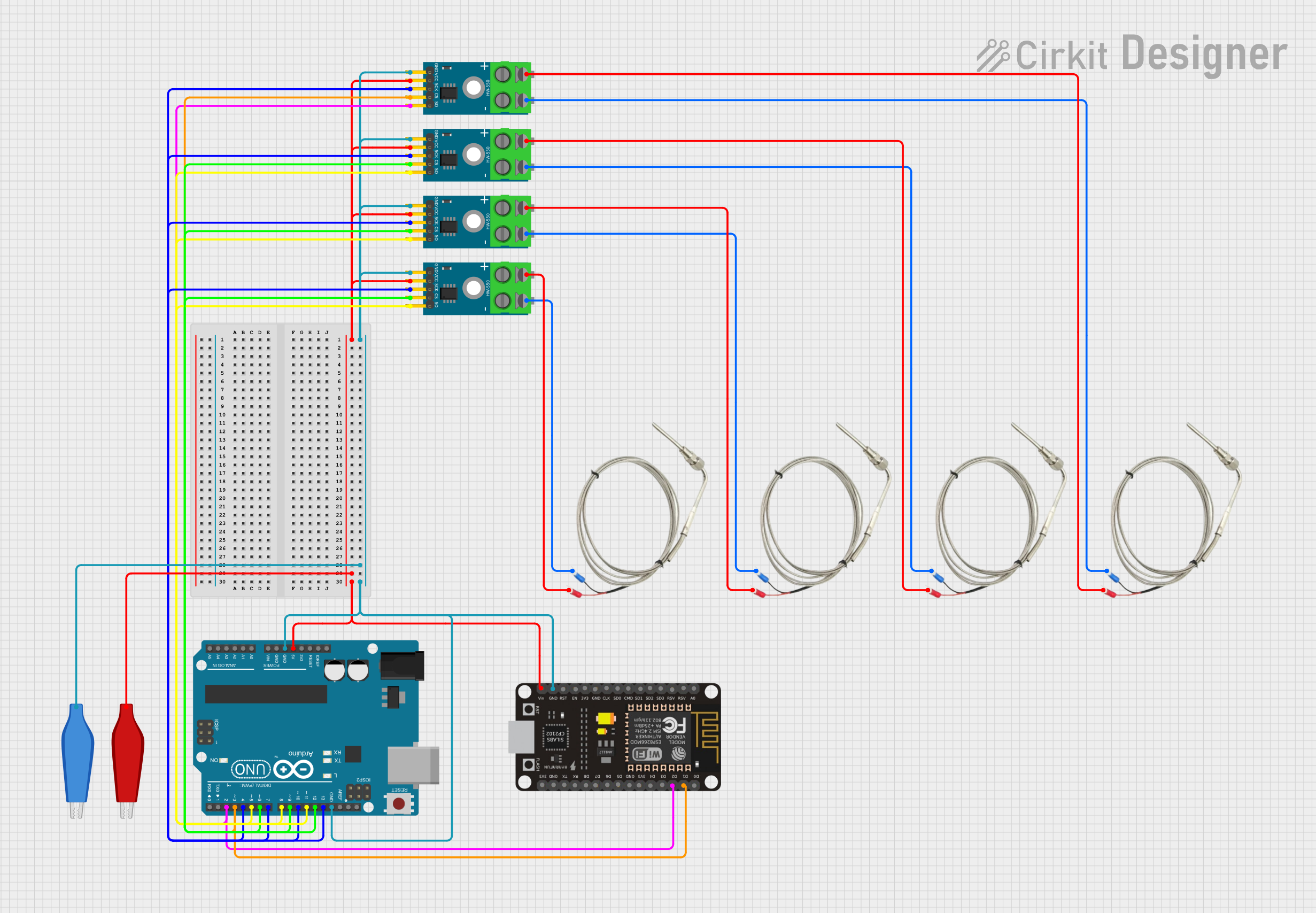
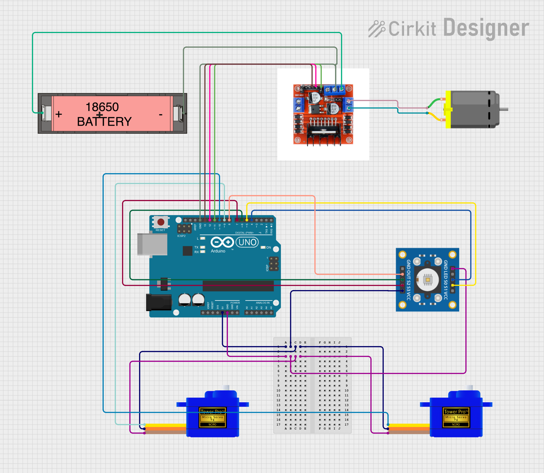
Explore Projects Built with AdaGator Side Yellow
Common Applications and Use Cases
- Rapid prototyping of electronic circuits
- Educational projects for learning electronics and programming
- Development of IoT (Internet of Things) devices
- Testing and debugging Feather-based designs
- Creating wearables and smart gadgets
Technical Specifications
Key Technical Details
- Compatibility: Designed for Adafruit Feather boards
- Connection Type: Solderless breadboard-style
- Dimensions: Matches the Adafruit Feather form factor
- Color: Yellow, for easy identification
Pin Configuration and Descriptions
| Pin Number | Description | Notes |
|---|---|---|
| 1 | GND (Ground) | Common ground for all circuits |
| 2-16 | General Purpose I/O (GPIO) | Digital and analog connections |
| 17 | 3V3 (3.3 Volts) | Power supply for low-voltage components |
| 18 | BAT (Battery Voltage) | Direct battery connection |
| 19 | USB (USB Voltage) | Power from USB connection |
| 20 | EN (Enable) | Enables or disables power to the Feather |
Note: The pin numbers and descriptions are illustrative. Refer to the Adafruit Feather board documentation for the exact pinout.
Usage Instructions
How to Use the Component in a Circuit
Insert the AdaGator Side Yellow into the Feather Board:
- Align the pins of the AdaGator Side Yellow with the corresponding headers on the Feather board.
- Gently press down to ensure a secure and proper connection.
Connecting Components:
- Insert components such as LEDs, resistors, sensors, etc., into the prototyping area.
- Use jumper wires to make connections between the Feather pins and your components.
Powering the Circuit:
- Power the Feather board through USB or an external battery.
- Ensure that the AdaGator Side Yellow is receiving power by checking the power indicator LED.
Important Considerations and Best Practices
- Voltage Levels: Ensure that all components connected to the AdaGator Side Yellow are compatible with the voltage levels provided by the Feather board (typically 3.3V).
- Current Limitations: Do not exceed the current limitations of the Feather board's GPIO pins.
- Short Circuits: Avoid creating short circuits, which can damage the Feather board and connected components.
- Static Discharge: Handle the AdaGator Side Yellow with care to prevent static discharge from damaging sensitive components.
Troubleshooting and FAQs
Common Issues Users Might Face
- Loose Connections: If your circuit is not working as expected, check for loose connections or components that may have come out of their slots.
- Power Issues: Ensure that the Feather board is properly powered and that the AdaGator Side Yellow is receiving power.
- Incorrect Wiring: Double-check your wiring against the circuit diagram to ensure all connections are correct.
Solutions and Tips for Troubleshooting
- Re-seat Components: If a component is not functioning, try re-seating it in the prototyping area.
- Use a Multimeter: A multimeter can help diagnose issues with power supply and connectivity.
- Check Feather Documentation: Refer to the documentation of your specific Feather board for any peculiarities or known issues.
FAQs
Q: Can I use the AdaGator Side Yellow with non-Feather boards? A: The AdaGator Side Yellow is designed specifically for Adafruit Feather boards. Using it with other boards may require modifications or may not be possible.
Q: How do I know if my circuit is drawing too much current? A: Measure the current draw with a multimeter. If it exceeds the specifications of the Feather board, you need to reduce the load or use external power sources for high-current components.
Q: Is soldering required to use the AdaGator Side Yellow? A: No, the AdaGator Side Yellow is designed for solderless prototyping. However, for permanent installations, soldering may be preferred for reliability.
Note: This documentation is a general guide and may not cover all aspects of the AdaGator Side Yellow. For specific projects or advanced usage, additional resources or expert advice may be necessary.