How to Use MLX90621: Examples, Pinouts, and Specs
Introduction
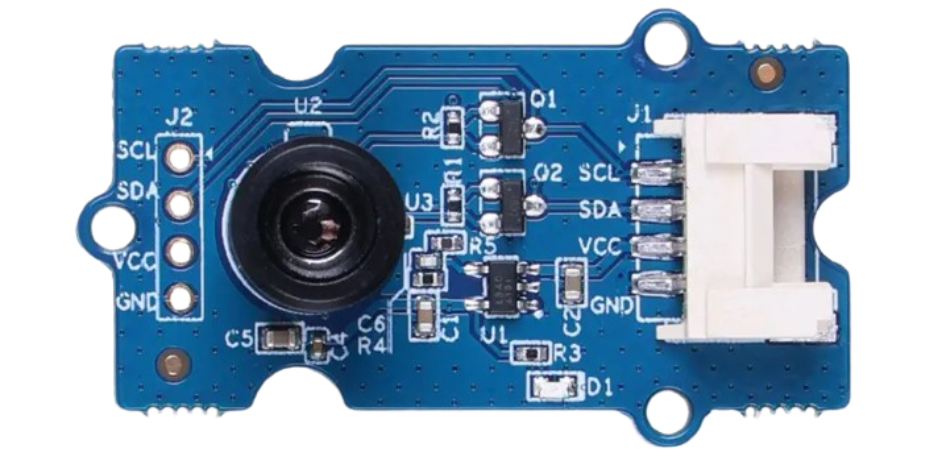
The MLX90621 is a compact, low-cost infrared thermal sensor designed for non-contact temperature measurement. It features a 16x4 pixel array, enabling the detection of temperature variations across a surface. This makes it ideal for applications such as thermal imaging, human body temperature monitoring, industrial process control, and home automation.
Explore Projects Built with MLX90621
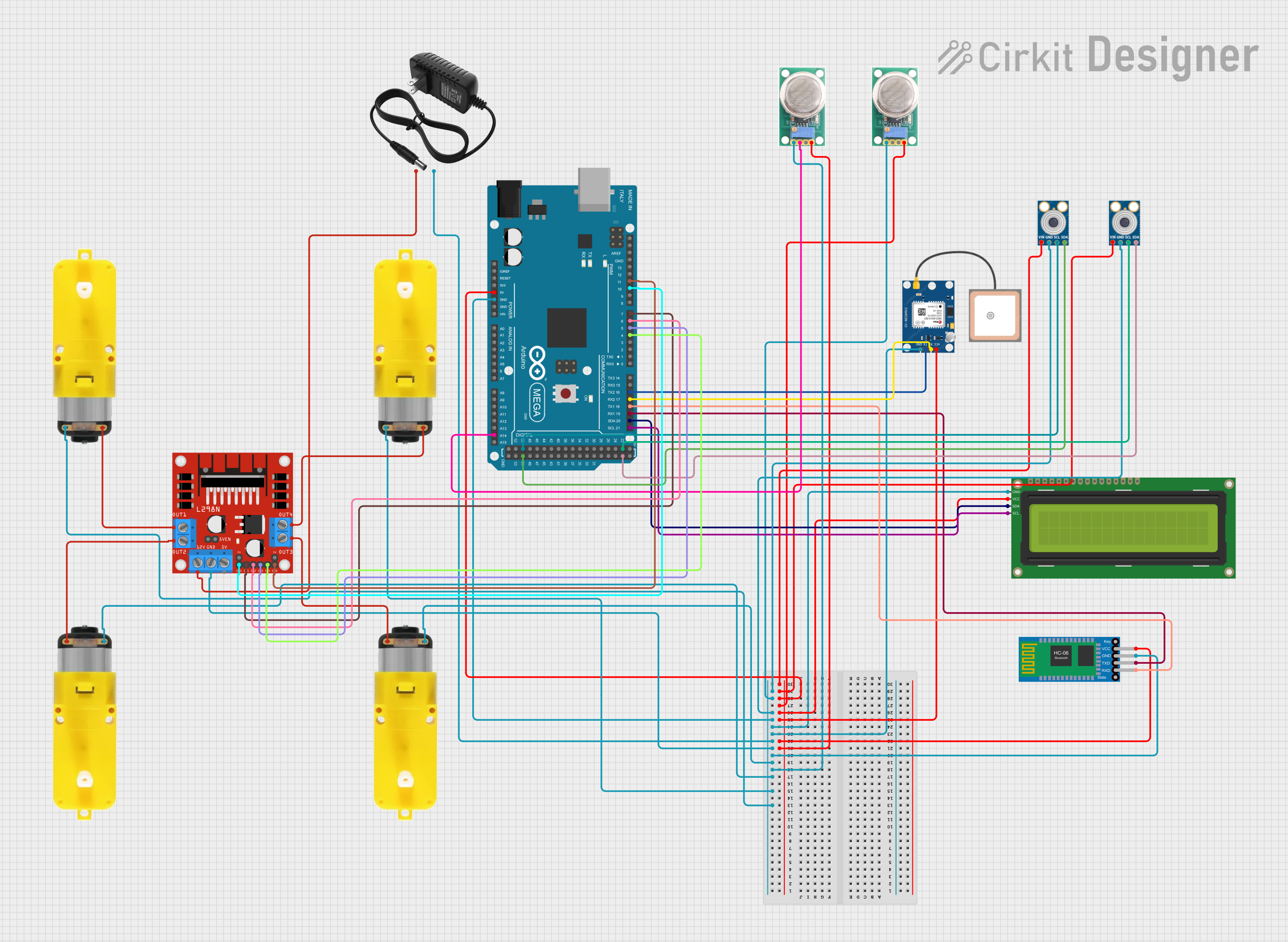
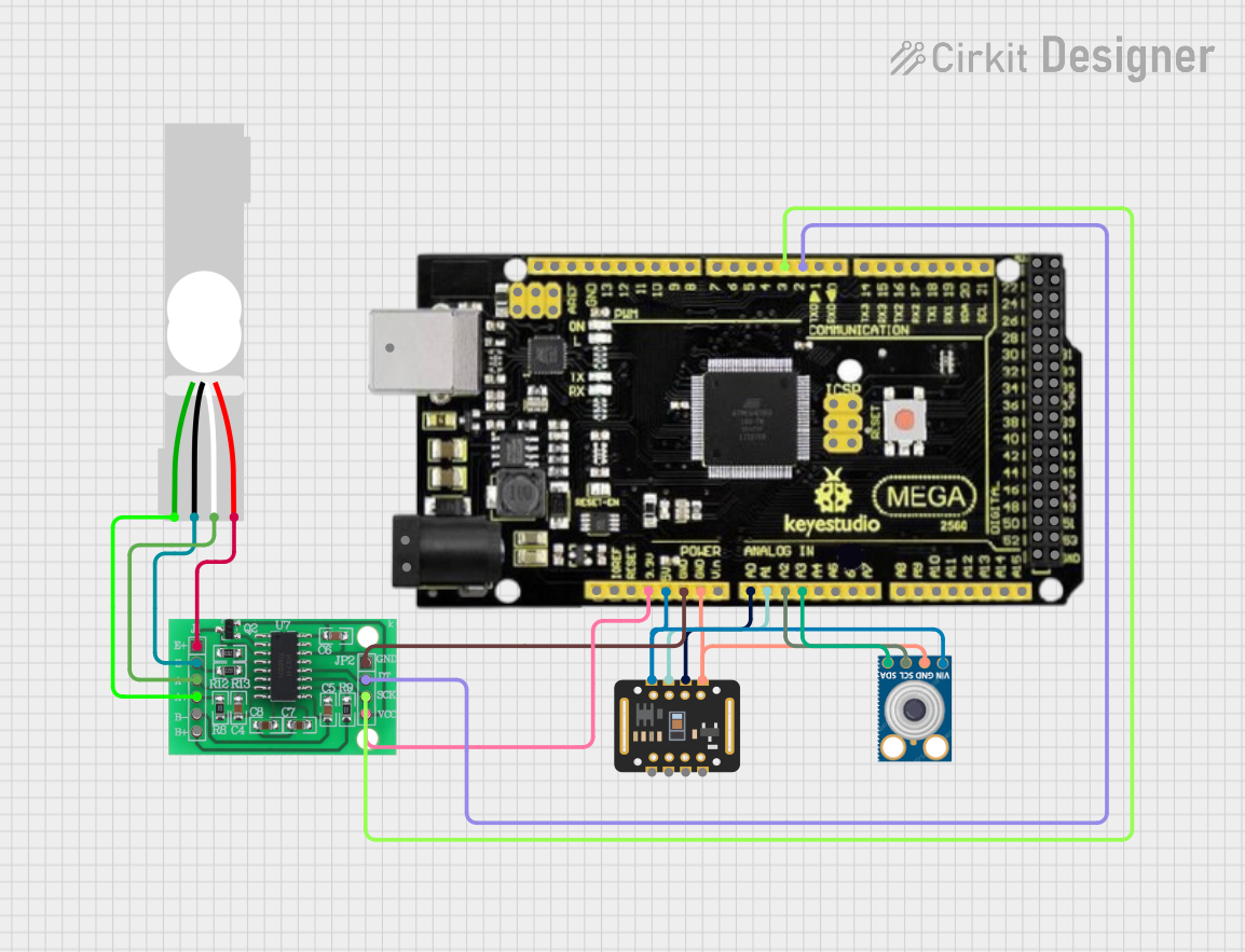
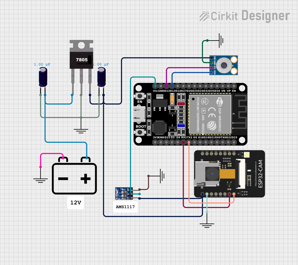

Explore Projects Built with MLX90621
Common Applications:
- Thermal imaging cameras
- Non-contact temperature measurement
- HVAC (Heating, Ventilation, and Air Conditioning) systems
- Industrial process monitoring
- Medical diagnostics and fever detection
- Smart home devices
Technical Specifications
The MLX90621 is a highly versatile sensor with the following key technical details:
Key Specifications:
| Parameter | Value |
|---|---|
| Operating Voltage | 3.0V to 3.6V |
| Current Consumption | 12mA (typical) |
| Temperature Range | -40°C to +85°C (ambient) |
| Object Temperature Range | -40°C to +300°C |
| Field of View (FoV) | 120° x 25° |
| Pixel Resolution | 16x4 (64 pixels) |
| Communication Interface | I²C (up to 1 MHz) |
| Measurement Accuracy | ±1°C (typical, depending on conditions) |
Pin Configuration:
The MLX90621 is typically available in a TO-39 package with the following pinout:
| Pin Number | Pin Name | Description |
|---|---|---|
| 1 | VDD | Power supply (3.0V to 3.6V) |
| 2 | SDA | I²C data line |
| 3 | SCL | I²C clock line |
| 4 | VSS | Ground |
Usage Instructions
The MLX90621 is straightforward to use in a circuit, especially with microcontrollers like the Arduino UNO. Below are the steps and best practices for integrating the sensor:
Connecting the MLX90621 to an Arduino UNO:
- Power Supply: Connect the
VDDpin to the 3.3V output of the Arduino and theVSSpin to the GND. - I²C Communication: Connect the
SDApin to the Arduino's A4 pin and theSCLpin to the A5 pin (for older Arduino boards) or the dedicated SDA/SCL pins on newer boards. - Pull-Up Resistors: Use 4.7kΩ pull-up resistors on the SDA and SCL lines to ensure proper I²C communication.
Sample Arduino Code:
The following code demonstrates how to read temperature data from the MLX90621 using the Arduino IDE. This example uses the Adafruit MLX90621 library.
#include <Wire.h>
#include <Adafruit_MLX90621.h>

// Create an instance of the MLX90621 object
Adafruit_MLX90621 mlx = Adafruit_MLX90621();

void setup() {
  Serial.begin(9600); // Initialize serial communication for debugging
  Serial.println("Initializing MLX90621...");

  // Initialize the MLX90621 sensor
  if (!mlx.begin()) {
    Serial.println("Failed to initialize MLX90621. Check connections!");
    while (1); // Halt execution if initialization fails
  }
  Serial.println("MLX90621 initialized successfully!");
}

void loop() {
  float temperatures[64]; // Array to store temperature readings

  // Read temperature data from the sensor
  mlx.readPixels(temperatures);

  // Print the temperature data to the Serial Monitor
  for (int i = 0; i < 64; i++) {
    Serial.print("Pixel ");
    Serial.print(i);
    Serial.print(": ");
    Serial.print(temperatures[i]);
    Serial.println(" °C");
  }

  delay(1000); // Wait 1 second before the next reading
}
Best Practices:
- Ensure the sensor is not exposed to direct sunlight or strong infrared sources, as this may affect accuracy.
- Use a stable 3.3V power supply to avoid fluctuations in readings.
- Keep the I²C lines as short as possible to minimize noise and interference.
- Calibrate the sensor if precise temperature measurements are required for your application.
Troubleshooting and FAQs
Common Issues:
Sensor Not Detected on I²C Bus:
- Cause: Incorrect wiring or missing pull-up resistors.
- Solution: Double-check the connections and ensure 4.7kΩ pull-up resistors are present on the SDA and SCL lines.
Inaccurate Temperature Readings:
- Cause: Environmental interference or improper calibration.
- Solution: Avoid placing the sensor near heat sources or reflective surfaces. Perform a calibration if necessary.
Arduino Freezes During Operation:
- Cause: I²C communication issues or insufficient power supply.
- Solution: Verify the power supply voltage and ensure proper pull-up resistor values.
FAQs:
Q: Can the MLX90621 measure the temperature of multiple objects simultaneously?
A: Yes, the 16x4 pixel array allows the sensor to measure the temperature of multiple objects within its field of view.
Q: What is the maximum distance for accurate temperature measurement?
A: The effective distance depends on the size of the object and its emissivity. For small objects, the sensor should be placed closer for accurate readings.
Q: Is the MLX90621 compatible with 5V microcontrollers?
A: The MLX90621 operates at 3.3V. If using a 5V microcontroller, level shifters are required for the I²C lines to prevent damage to the sensor.
By following this documentation, you can effectively integrate and use the MLX90621 in your projects.